Tunable controlled laser array

a laser array and control technology, applied in the field of lasers, can solve the problems of difficult to tune dfb lasers to other wavelengths, difficult to cover a large part of a communication band,

Inactive Publication Date: 2005-07-05
NEOPHOTONICS CORP
View PDF101 Cites 60 Cited by
  • Summary
  • Abstract
  • Description
  • Claims
  • Application Information

AI Technical Summary

Benefits of technology

[0009]These and other aspects of the present invention will be more readily understood when considered with respect to the following description and accompanying figures.

Problems solved by technology

DFB lasers, however, generally operate at fixed wavelengths, and are very difficult to tune to other wavelengths.
Though slight changes in wavelength can be realized via thermal effects, tuning DFB lasers by large amounts, to cover a large part of a communication band is often not possible.
However, system reconfiguration becomes more complex in order to accommodate multiple DFB lasers.
To overcome these shortcomings, a great deal of effort has been expended on fabricating tunable laser diodes.
Unfortunately, delivering the performance of fixed wavelength DFB lasers with the added benefit of wide tunability at an appropriate cost is not easily accomplished.
Varying the optical path length of the controlling element significantly induces other complexities that degrade the performance of the laser.

Method used


Image

  • Tunable controlled laser array
  • Tunable controlled laser array
  • Tunable controlled laser array

Examples


embodiment 1300

[0059]FIG. 13 illustrates an EO deflector embodiment 1300 of the present invention, in which EO deflector 120 is used to steer the optical beam. As in previous embodiments, optical beam 99 from particular lens element 7 of laser array 5 is collimated with fixed lens 121, and then transmitted to EO deflector 120 which steers collimated beam 125 to the focusing lens 128. Focusing lens 128, in turn, directs the axis of the cone of light 98 to be focused on, and maximally coupled to, fiber 15. A electro-optic modulator exhibits a predetermined amount of birefringence upon application of a voltage to a suitable crystalline material producing the birefringent effect. Although some materials are known to be naturally birefringent, others become birefringent only when a voltage is applied, thereby allowing for the presence and degree of birefringence to be controlled. Examples of suitable materials include, without limitation, barium sodium niobate, lithium niobate, potassium dihydrogen pho...

embodiment 1400

[0060]FIG. 14 illustrates an AO embodiment 1400 of the present invention, in which AO deflector 130 is used to steer the optical beam. As in previous embodiments, optical beam99 from particular lens element 7 of laser array 5 is collimated with fixed lens 131, and then transmitted to AO modulator 130, which steers collimated beam 135 to the focusing lens 138. Focusing lens 138, in turn, directs the axis of the cone of light 98 to be focused on, and maximally coupled to, fiber 15. Typically in an AO deflector, an optical beam is diffracted by a column of sound passing through a suitable AO medium. An acousto-optic interaction occurs in an optical medium, for example, when an acoustic wave and a laser beam are present in the medium. When an acoustic wave is launched into the optical medium, it generates a refractive index wave that behaves like a sinusoidal grating. In general, it is desirable to couple a piezoelectric transducer to the AO medium, because a predetermined voltage appli...


PUM


Abstract

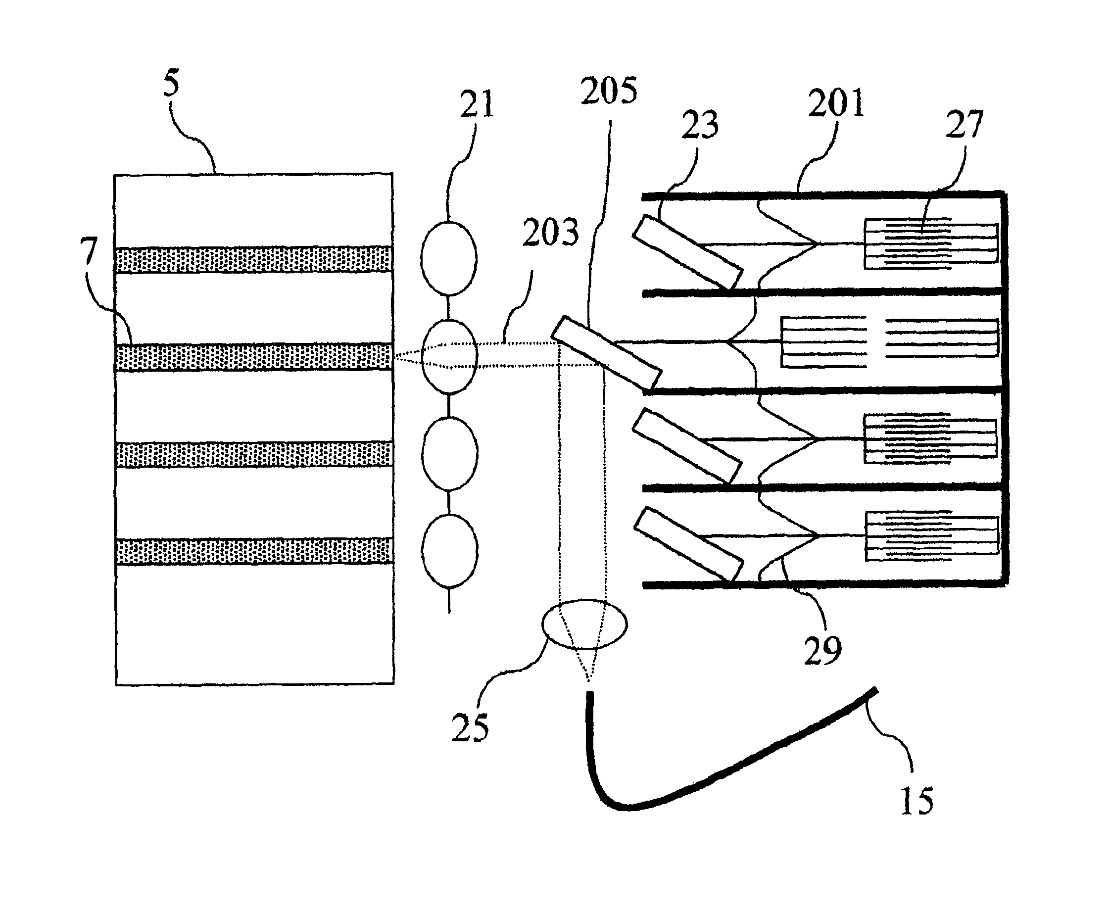
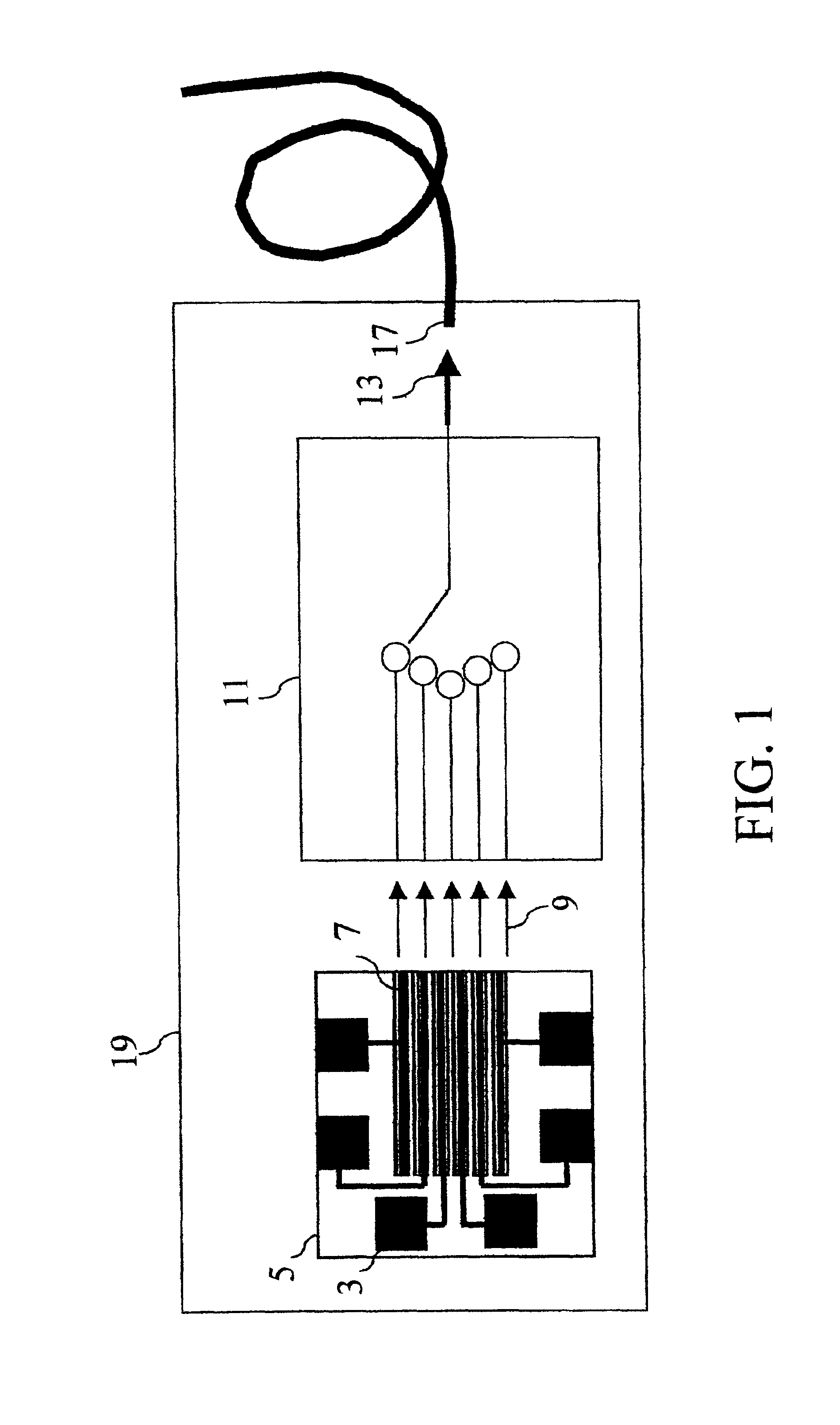
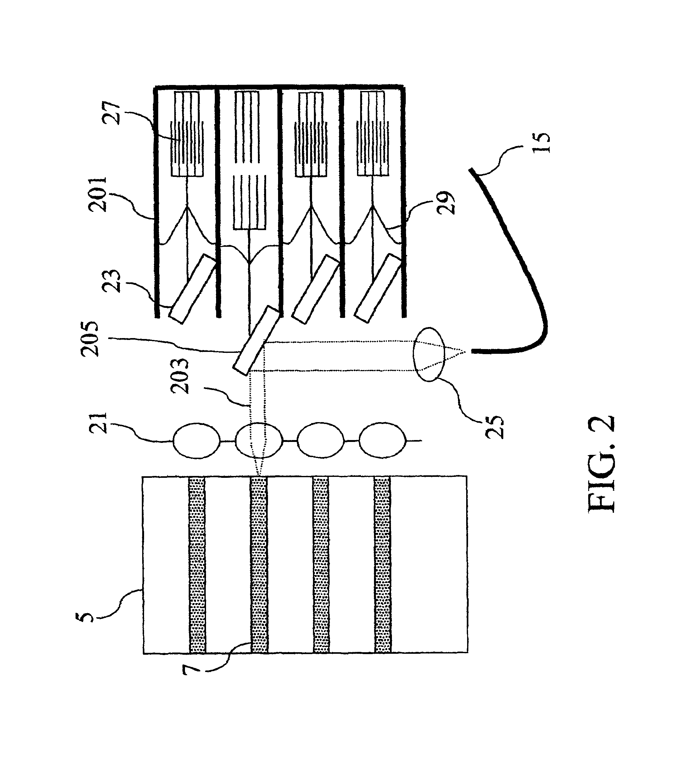
A semiconductor laser capable of emitting in any one of standard communication wavelengths is of great practical value. To this end, a single semiconductor chip is fabricated on which many different distributed feedback (DFB) lasers are integrated. The device parameters of the different DFB lasers are varied such that each laser emits at a different wavelength. In addition a micro-mechanical optical element is packaged with the laser array, such that the position of the optical element controls which laser stripe is coupled to the output fiber. The micro-mechanical element or switch in various embodiments is a sliding waveguide, a movable lens, or a mirror that tilts. By selecting the particular DFB laser, controlling the temperature to fine tune the wavelength, and adjusting the position of the micro-mechanical optical element, the output wavelength is set to one of many communication wavelengths.

Description

CROSS-REFERENCE TO RELATED APPLICATIONS[0001]This application claims the benefit of U.S. provisional application numbers 60 / 244,689 filed Oct. 30, 2000, 60 / 244,645 filed Oct. 30, 2000, 60 / 244,738 filed Oct. 31, 2000 and 60 / 307,559 filed Jul. 24, 2001 which are hereby incorporated by reference as if set forth in full herein.BACKGROUND[0002]The present invention relates generally to lasers and in particular to tunable lasers used in telecommunications systems.[0003]Lasers are widely used in high speed data communication devices such as multi-wavelength fiber optic communication links. In wavelength division multiplexed (WDM) communication links, the transmission of data via an optical fiber is increased by using multiple optical signals with different wavelengths simultaneously. Each optical signal is capable of carrying a different data signal.[0004]Conventional optical sources for such links are often fixed wavelength distributed feedback (DFB) lasers. DFB lasers contain a waveguidi...

Claims


Application Information

Patent Timeline
Patent Type & Authority Patents(United States)
IPC IPC(8): G02B26/08G02B6/32G02B6/42H01S5/40H01S5/00H01S5/022H01S5/12G02B26/00H01S5/22
CPCG02B6/32G02B6/4225G02B6/4234G02B26/00G02B26/0816G02B26/0833G02B26/0841G02B26/085G02B26/0858G02B26/0866H01S5/4031G02B6/4249H01S5/005H01S5/02284H01S5/1215H01S5/4087H01S5/02251
Inventor PEZESHKI, BARDIAHEANUE, JOHNVAIL, ED
Owner NEOPHOTONICS CORP
Why Eureka
Try Eureka