
Ceramic material resistant to halogen plasma and member utilizing the same

Inactive Publication Date: 2005-07-12
KYOCERA CORP
View PDF36 Cites 222 Cited by
  • Summary
  • Abstract
  • Description
  • Claims
  • Application Information

AI Technical Summary

Benefits of technology

[0017]An object of the present invention is to provide a ceramic material having increased resistance to corrosion in a plasma of a corrosive halogen-based gas.
[0018]Another object of the present invention is to provide a member having increased resistance to corrosion in plasma of the corrosive halogen-based gas.
[0019]An further another object of the present invention is to provide a transparent member having increased resistance to corrosion in the plasma of the corrosive halogen-based gas.

Problems solved by technology

However, glass or quartz which have hitherto been used, exhibit an insufficient corrosion resistance in the plasma and are quick to wear.
In particular, there has been a problem in that a contact surface when contacting a plasma of chlorine tends to be etched off, accompanied in change in surface property and that in the case of a member that requires a light transmissivity, the light transmissivity tends to be lowered as a result of the surface progressively fogged up.
Even the members utilizing a metal such as stainless steel has so insufficient a corrosion resistance as to constitute a cause of occurrence of rejected products during the manufacture of semiconductor devices due to corrosion.
Also, even with the conventional sintered body of alumina, sapphire or aluminum nitride, the surface tends to be corroded in contact with the chloride plasma to such an extent that no separation of crystalline particles forming the surface can be avoided, and fine particles separated from the surface will stick to a support surface of the electrostatic chuck and the semiconductor wafer with the film forming accuracy consequently affected badly.
Moreover, inconveniences have been encountered that affected by a physical influence, brought about by, for example, light, heat and / or ions generated in the plasma within the device, and / or a chemical reaction with active species and the corrosive gas, a transparent windowpane for the windows is susceptible to progressive surface corrosion and consequent surface fogging to such an extent that observation of the interior of the device and analysis of the plasma will no longer be carried out.
For this reason, a situation has arisen that there is no way other than to install the window material at a location distant from the plasma.
An alumina-coated glass material disclosed in the Japanese Laid-open Patent Publication No. 8-27566-A has been found having problems in that alumina itself has an insufficient resistance to corrosion brought about by the halogen plasma and that because of a difference in coefficient of thermal expansion between the alumina film and the glass base, not only does separation of the film tend to occur, but also the film is susceptible to cracking.

Method used


Image

  • Ceramic material resistant to halogen plasma and member utilizing the same
  • Ceramic material resistant to halogen plasma and member utilizing the same
  • Ceramic material resistant to halogen plasma and member utilizing the same

Examples


embodiment 1

[0073]In this embodiment, the corrosion resistance of the ceramic material of the present invention made up of the composite metal oxide was tested.

[0074]Using various oxide powders, samples listed in Table 1 were prepared. Referring to Table 1, Samples 1 to 5 were prepared by melting a mixture of oxides of the metals of Group IIIa of Periodic Table and SiO2 and / or Al2O3 at 2,000° C. and quenching it to vitrify. Samples 6 to 9 were prepared by firing the compacts mixed of Y2O3 or Yb2O3 and SiO2 in respective predetermined proportions, at 1,300 to 1,600° C. Samples. 10 to 15 were prepared from the compacts of mixtures of Y2O3 and Al2O3 which were fired in the oxidizing or vacuum atmosphere at 1,600 to 1,900° C. Samples 16 to 18 were prepared from the compact of mixture of Al2O3 and the metal oxide of Group IIIa of the Periodic Table which were fired at 1,400 to 1,750° C. Samples 19 and 20 were prepared by vapor depositing Sc2O3 or La2O3 and Al2O3 on a targets with the use of a sputte...

embodiment 2

[0085]In this embodiment, specific examples of the plasma-resistant members are directed to a member used in the plasma processing apparatus for use in manufacture of semiconductor devices.

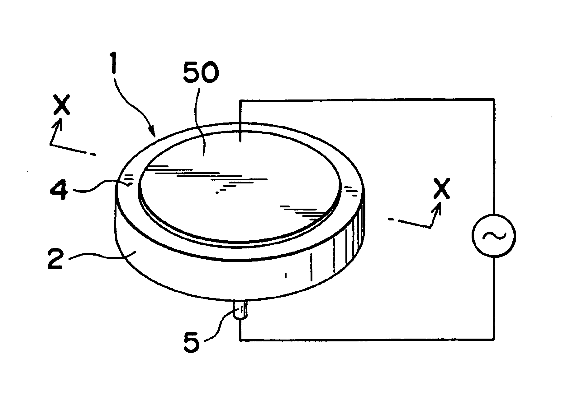
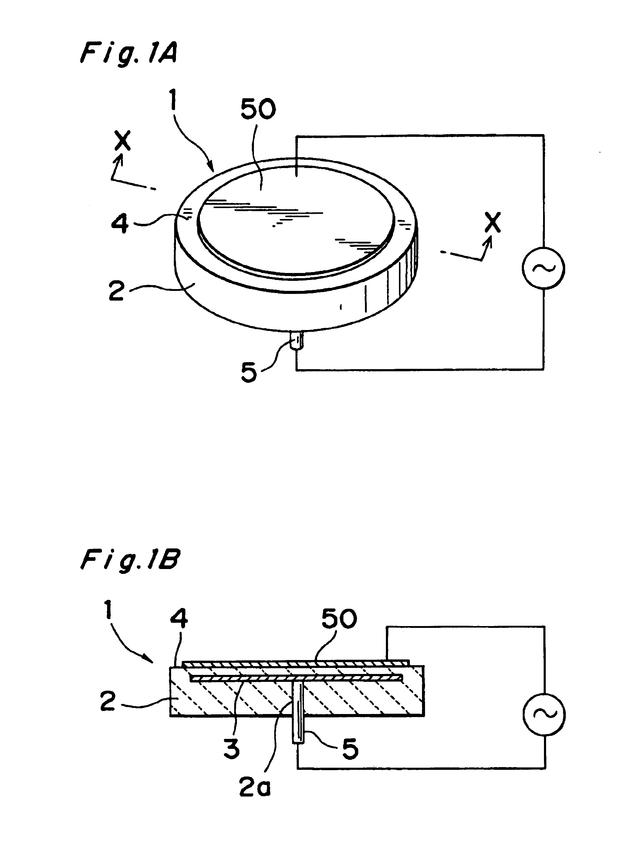
[0086]As a first example of use of the plasma-resistant member of the present invention, FIG. 1A illustrates an outer appearance of an electrostatic chuck and FIG. 1B illustrates a section of the electrostatic chuck. The electrostatic chuck is in the form of a plate-like body 2 prepared from the YAG sintered body of the present invention, and the plate-like body 2 has a suction electrode 3 embedded therein and has an upper surface serving as a support surface 4, an undersurface of said plate-like body 2 having a power supply end extending therethrough for connection with the suction electrode 3.

[0087]The YAG sintered body has a porosity not higher than 3% and the support surface 4 at the upper surface of the plate-like body 2 after having been formed is precisely machined to the center average rou...

embodiment 3

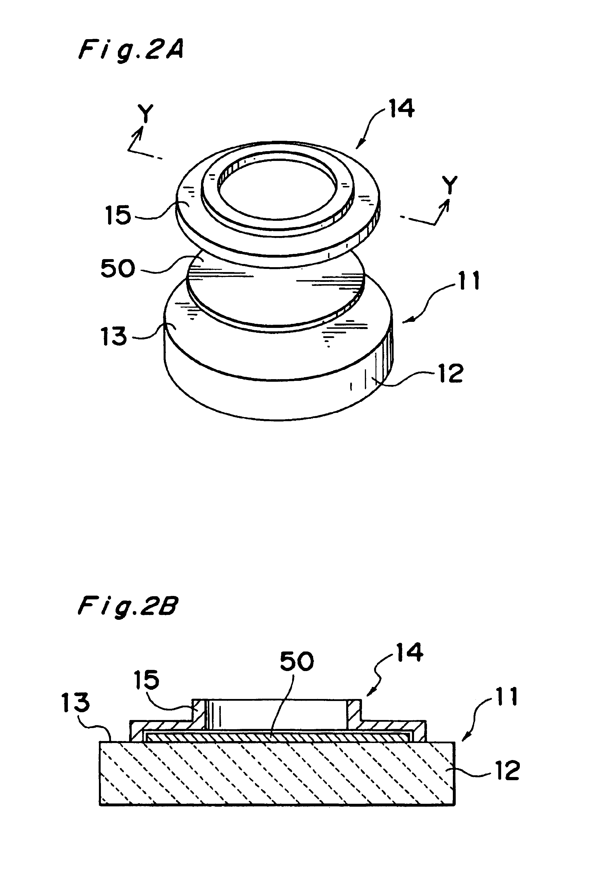
[0116]In this embodiment of the present invention, a window member for the plasma processing apparatus is dealt with. The window member is provided as a light transmissive window 67 in a portion of a side wall 1 within the plasma processing apparatus such as, for example, shown in FIG. 6. As shown in FIGS. 5A and 5B, the window 67 is fixed within the apparatus with a window member 21 accommodated in a frame 83 that is fixed to the side wall 81(1).

[0117]The window member 21 of the present invention is made from the plate-like YAG sintered body having a high light transmissivity. The window member 21 in the manner as shown in FIG. 5A is formed only from the light transmissive YAG sintered body, in which case the thickness thereof is required to be 0.5 to 10.0 mm. This is because if the thickness of the window member formed only from the light transmissive YAG sintered body is thinner than 0.5 mm, it will lack a sufficient mechanical strength for the window member of the plasma process...


PUM

PropertyMeasurementUnit
Thicknessaaaaaaaaaa
Lengthaaaaaaaaaa
Fractionaaaaaaaaaa

Abstract

A member used within a plasma processing apparatus and exposed to a plasma of a halogen gas such as BCl3 or Cl2 is formed from a sintered body of metals of Group IIIa of Periodic Table such as Y, La, Ce, Nd and Dy, and Al and / or Si, for example, 3Y2O3.5Al2O3, 2Y2O3.Al2O3, Y2O3.Al2O3 or disilicate or monosilicate, and in particular, in this sintered body, the content of impurity metals of Group IIa of Periodic Table contained in the sintered body is controlled to be 0.15 wt % or more in total. Specifically, for this member, an yttrium-aluminum-garnet sintered body having a porosity of 3% or less and also having a surface roughness of 1 μm or less in center line average roughness Ra is utilized.

Description

[0001]This is a divisional of application Ser. No. 09 / 031,401, now U.S. Pat. No. 6,447,937, filed Feb. 26, 1998, which application is hereby incorporated by reference in its entirety.BACKGROUND OF THE INVENTION[0002]1. Field of the Invention[0003]The present invention relates to a corrosion-resisting ceramic material having high resistance to corrosive halogen-based gases and, more particularly, to a halogen-plasma resisting member in a plasma processing apparatus.[0004]2. Prior Art[0005]The halogen plasma technology is utilized in a semiconductor fabricating process, discharging tubes and lamps. The plasma in a corrosive halogen-based gas containing fluorine and / or chlorine, which has high reactivity, is utilized to facilitate growth from the gas phase, etching and cleaning during fabrication of a semiconductor device. Byway of example, a halogen plasma device includes a CVD device or a sputtering device for formation of a film on a semiconductor wafer, and an etching device for mi...

Claims


Application Information

Patent Timeline
IPC IPC(8): C04B35/50C04B35/18
CPCC04B35/18C04B35/44Y10T428/26Y10T428/249953
Inventor MURAKAWA, SHUNICHIITOH, YUMIKOAIDA, HIROSHINAKAMURA, KATSUMIHAYASAKI, TETSUZI
Owner KYOCERA CORP
Learn More