Process for manufacturing fluoroolefins

a technology of fluoroolefins and manufacturing processes, applied in the field of manufacturing fluoroolefins, can solve the problems of difficult separation, low economic viability of the process, and high amount of cosub>2, and achieve the effects of less separation efforts, efficient yield and elimination of hydrochloric acid waste streams

Inactive Publication Date: 2005-07-19
3M INNOVATIVE PROPERTIES CO
View PDF62 Cites 12 Cited by
  • Summary
  • Abstract
  • Description
  • Claims
  • Application Information

AI Technical Summary

Benefits of technology

[0012]We have found a process for manufacturing TFE that may have an efficient yield (overall yield preferably is higher than 90% based on a hydrocarbon feed) and may eliminate a hydrochloric acid waste stream. The process of the present invention may also produce HFP and can thus be used to make both TFE and HFP if desired. The process generally involves less separation efforts to purify TFE, can be designed in a cost efficient manner, and can be designed as a so-called closed-loop in which no or very low amounts of waste material is created. This closed-loop process is environmentally advantageous.

Problems solved by technology

This process produces equimolar amounts of aqueous hydrochloric acid and considerable amounts of partially fluorinated and chlorinated compounds, which are difficult to separate from TFE to obtain polymerization grade TFE (U.S. Pat. No. 4,898,645).
The fluorinated and other side products have to be incinerated through thermal oxidizers, which is another costly process and produces high amounts of CO2.
But this process is hardly economically viable due to the use of costly elemental fluorine and the high-energy consumption involved.
This technology still requires high-energy consumption.
Accordingly, substantial waste material is produced with this process, which causes an environmental burden and makes the process economically less attractive.
Additionally, the process requires the use of TFE as one of the starting compounds, which creates an additional economical disadvantage as part of the TFE produced is needed to produce further TFE.
The fluorocarbons to be pyrolyzed are obtained from exhaustive fluorination of petroleum fractions using elemental fluorine, which renders the process economically unattractive.
These processes cannot replace the standard technology via R22, because the technology does not produce new C—F-bonds and therefore cannot meet the demand for TFE.

Method used


Image

  • Process for manufacturing fluoroolefins
  • Process for manufacturing fluoroolefins
  • Process for manufacturing fluoroolefins

Examples


example 1

Simons Electrochemical Fluorination of Octane

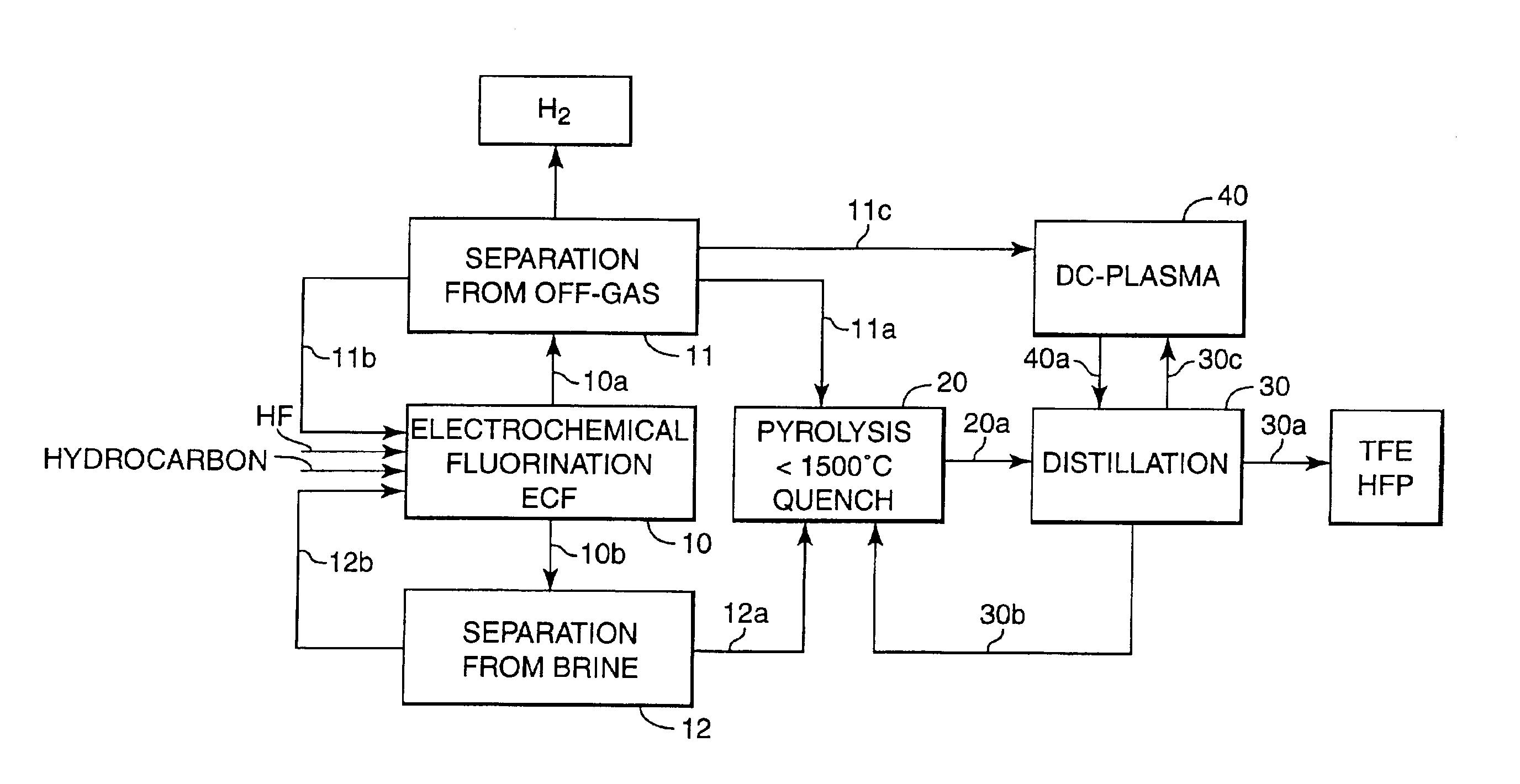
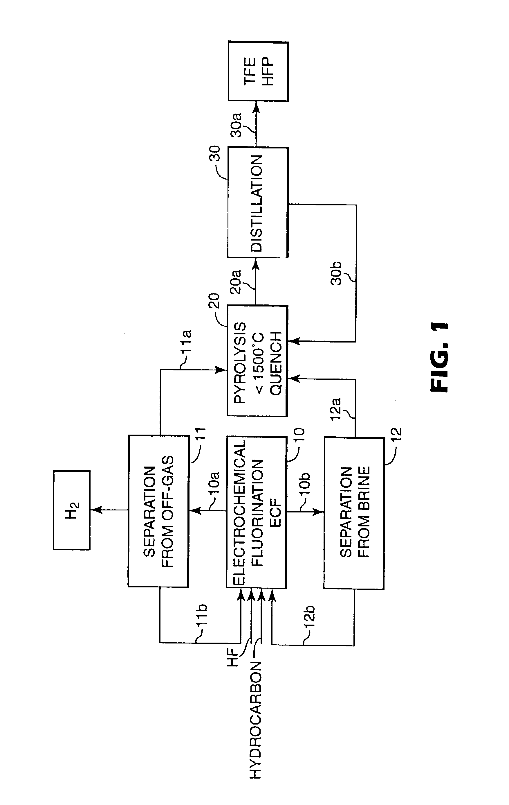
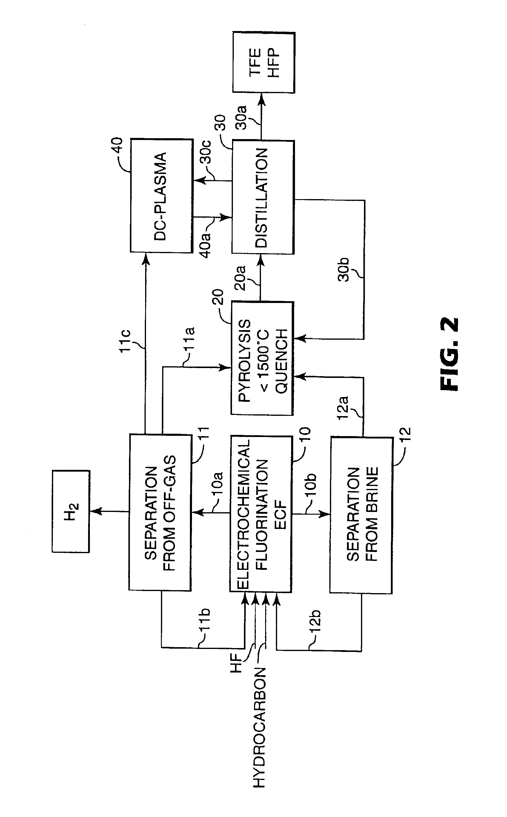
[0064]A 1-liter electrochemical fluorination cell of the type described in U.S. Pat. No. 2,567,011, equipped with 2 overhead condensers having a nickel anode with a surface area of 0.037 m2 was charged with 1000 grams C6F14, 40 grams of dimethyldisulfide, 40 grams of octane and 200 grams of anhydrous HF. The cell was operated at 45° C. and 2 bar. Voltage was between 5-6 Volts, current density about 1500 A / m2. Voltage was reduced for 4 seconds to less than 4 Volts causing the current to fall to essentially zero after each 80 seconds (“intermitted current”). Octane was continuously fed to the cell to maintain its concentration in the circulating fluorochemical phase at about 5 wt %. Circulation rate was varied from 0.3 to 1 cell volume / hour with an external pump without an observably distinct effect on the fluorination rates.

[0065]The experiment was run for 500 hours. Intermittently, a portion of the fluorochemical phase was removed, the pe...

example 2

Membrane Process

[0067]The off-gas stream emanating from the ECF cell behind the overhead condensers at the run of Example 1 contained about 1.7 volume % of perfluorinated alkanes. Typical composition is shown in Table 1.

[0068]

TABLE 1Composition of off-gas; balance H2ComponentsCF4C2F6C3F8C4F10C3F12CHF3TotalVolume %0.250.420.20.440.20.11.61

The off-gas stream was washed with aqueous NaOH solution, filtered to remove any liquid and solid particles compressed to 8 bar and fed to a 2-stage membrane system consisting of a polyimide, asymmetric composite hollow fiber membrane. A MEDAL™ Gas separation process from Air Liquide, Houston, Tex., according to Example 4 of U.S. Pat. No. 5,814.127 was used. The output of the 2nd membrane module yielded 99.9% fluorocarbon with less than 0.1% H2, the composition of which is given in Table 2. The “waste-stream” contained 99.7% hydrogen. The recovered fluorocarbons can be directly used as carrier gas at the DC plasma pyrolysis and also as feedstock for...

example 3

Preparation of TFE Via DC-plasma Pyrolysis

[0070]A 30 kW DC plasma torch was used as described in WO 01 / 58841. Presence of carbon was given by “self-consuming” carbon electrodes. Dry quenching was used. The efficiency of this method is illustrated with pure fluorocarbons (Table 3) and the fluorocarbon mixture from the off-gas of Example 2 (Table 4). The carrier gas used was CF4. The CF4 stream was fed through a vaporizer containing the investigated fluorocarbons. Flow rate was varied from about 3.5 to 7.5 kg / hr. Results are shown in Table 3.

[0071]

TABLE 3DC plasma pyrolysis of selected fluorocarbonsPerfluorinatedFeed RateFlow Rate kg / hrFeedkg / hrof quenched reaction mixtureotherStock*FeedCF4CF4C2F4C3F6FC'sC8F18 (FC 3225)0.453.01.71.20.150.4C7F16 (PF 5070)1.704.94.21.70.10.6C7F16 (PF 5070)1.533.02.41.30.00.8C6F14 (PF 5060)2.864.03.52.40.40.6C5F12 (PF 5050)4.403.03.73.70.0*The Perfluorinated Feed Stock is available from 3M Company, St. Paul, MN. HFP was produced with very low yields.

Tab...


PUM

PropertyMeasurementUnit
boiling pointaaaaaaaaaa
temperatureaaaaaaaaaa

Abstract

A process for manufacturing fluoroolefins comprising perfluorinating a starting material comprising at least one carbon-bonded hydrogen by electrochemical fluorination, dissociating this separated effluent in a pyrolysis, quenching and separating the effluent to yield tetrafluoroethylene and / or hexafluoropropylene.

Description

FIELD OF INVENTION[0001]This invention relates to a process for manufacturing fluoroolefins. More particularly, the present invention relates to using electrochemical fluorination and a pyrolysis to manufacture tetrafluoroethylene and / or hexafluoropropylene.BACKGROUND OF INVENTION[0002]Tetrafluoroethylene (TFE) and hexafluoropropylene (HFP) are widely used as monomers in the manufacture of plastic and elastomeric fluoropolymers. See, for example, J. Scheirs in Modern Fluoropolymers, Wiley, 1996. The worldwide consumption of TFE exceeds 105 tons / year. HFP is used as a comonomer to manufacture thermoplastic and elastomeric fluoropolymers and as starting material for making hexafluoropropene oxide (HFPO). The worldwide consumption is estimated to be 30,000 tons / year.[0003]There are several known methods for manufacturing TFE and HFP. The most common method and almost exclusively used at industrial scale, involves pyrolyzing CHClF2 (R-22). See for example, U.S. Pat. No. 2,551,573. The h...

Claims


Application Information

Patent Timeline
Patent Type & Authority Patents(United States)
IPC IPC(8): C07C21/00C07C21/185C07C21/18C07C17/23C07C17/269C07C17/00C07C17/361C25B3/08C25B3/00C25B3/28
CPCC07C17/23C07C17/269C25B3/08C07C21/18C07C21/185C07C17/361C25B3/28
Inventor BAUER, GERALD L.WEIGELT, JEFFREY D.HINTZER, KLAUSLOEHR, GERNOTSCHWERTFEGER, WERNERPONELIS, ARTHUR A.
Owner 3M INNOVATIVE PROPERTIES CO
Why Eureka
Try Eureka