Optical system for simultaneous imaging of LWIR and millimeter wave radiation

a simultaneous imaging and optical system technology, applied in the field of optical systems, can solve the problems of blocking infrared electromagnetic energy, unable to provide imaging systems, and the resolution of millimeter wave systems is generally poor, so as to achieve the effect of reducing the wavelength of millimeter wave radiation

Inactive Publication Date: 2005-07-19
RAYTHEON CO
View PDF7 Cites 18 Cited by
  • Summary
  • Abstract
  • Description
  • Claims
  • Application Information

AI Technical Summary

Benefits of technology

[0011]The need in the art is addressed by the system and method for simultaneous imaging of both infrared and millimeter wave radiation of the present invention. The novel optical system includes a primary mirror, a Mangin secondary mirror positioned to receive energy reflected from the primary mirror, and an immersion lens for focusing energy received from the Mangin mirror. In the illustrative embodiment, the primary mirror and Mangin mirror are arranged in a Cassegrain configuration. Central to this invention is the use of a negative power refractive Mangin mirror as the Cassegrain secondary mirror, so that the field curvature of the secondary mirror and immersion lens can be made to cancel. The immersion lens effectively decreases the wavelength of the millimeter wave radiation, allowing a smaller detector to collect the same amount of radiation as would a larger detector in air. In the illustrative embodiment, the system further includes a detector array placed in intimate contact with the immersion lens.

Problems solved by technology

Rain, fog, or smoke may block infrared electromagnetic energy.
However millimeter wave systems typically generate images with relatively poor resolution compared to infrared systems.
Currently, no system is available which is capable of imaging in response to both infrared and millimeter wave radiation.
However, this approach would be costly and impractical for most applications.

Method used


Image

  • Optical system for simultaneous imaging of LWIR and millimeter wave radiation
  • Optical system for simultaneous imaging of LWIR and millimeter wave radiation
  • Optical system for simultaneous imaging of LWIR and millimeter wave radiation

Examples


Embodiment Construction

[0015]Illustrative embodiments and exemplary applications will now be described with reference to the accompanying drawings to disclose the advantageous teachings of the present invention.

[0016]While the present invention is described herein with reference to illustrative embodiments for particular applications, it should be understood that the invention is not limited thereto. Those having ordinary skill in the art and access to the teachings provided herein will recognize additional modifications, applications, and embodiments within the scope thereof and additional fields in which the present invention would be of significant utility.

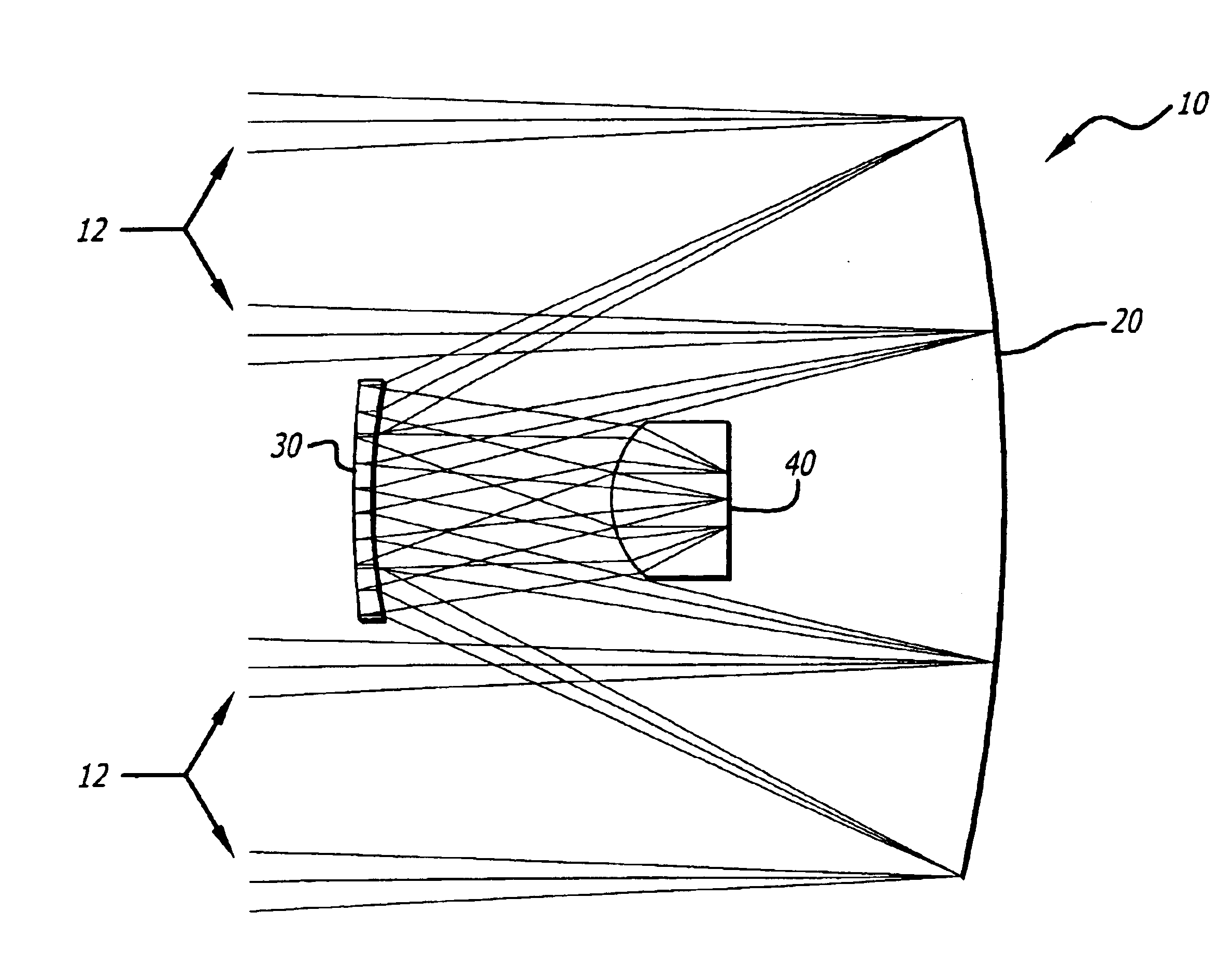
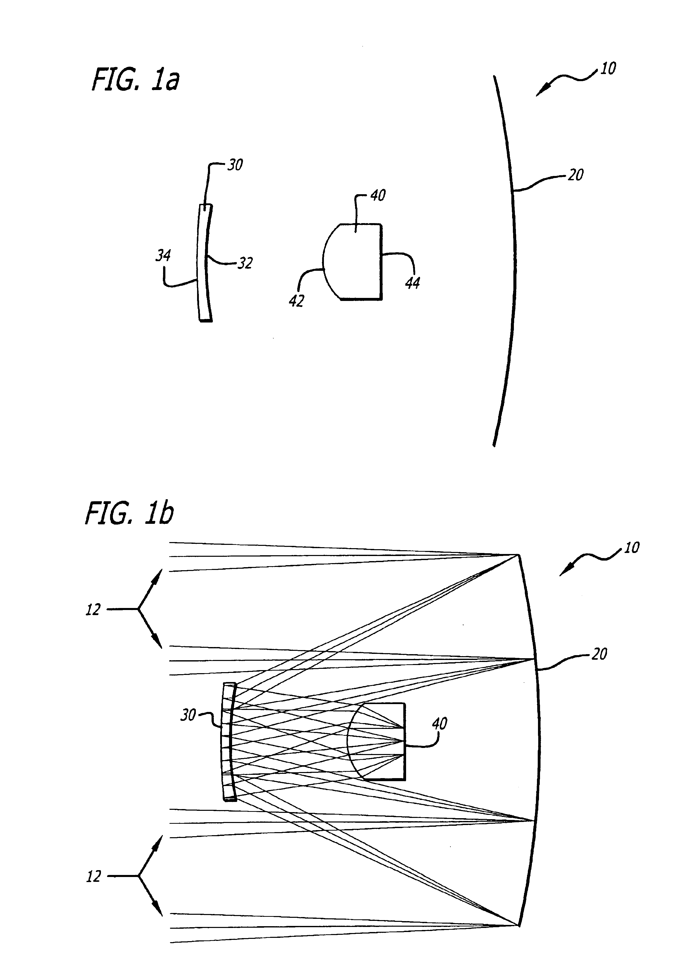
[0017]The present invention is a catadioptic (meaning using both mirrors and lenses) optical system resembling a Cassegrain configuration that is specially designed to accommodate both infrared and millimeter wave radiation. FIG. 1a is an optical schematic of an illustrative embodiment of the optical system 10 of the present invention. FIG. 1b shows ...


PUM


Abstract

A system and method for simultaneous imaging of both infrared and millimeter wave radiation. The novel optical system (10) includes a primary mirror (20), a Mangin secondary mirror (30) positioned to receive energy reflected from the primary mirror (20), and an immersion lens (40) for focusing energy received from the Mangin mirror (30). In the illustrative embodiment, the primary mirror (20) and Mangin mirror (30) are arranged in a Cassegrain configuration. Central to this invention is the use of a negative power refractive Mangin mirror (30) as the Cassegrain secondary mirror, so that the field curvature of the secondary mirror (30) and immersion lens (40) can be made to cancel. The immersion lens (40) effectively decreases the wavelength of the millimeter wave radiation, allowing a smaller detector to collect the same amount of radiation as would a larger detector in air. In the illustrative embodiment, the system (10) further includes a detector array (52) placed in intimate contact with the immersion lens (40).

Description

BACKGROUND OF THE INVENTION[0001]1. Field of the Invention[0002]The present invention relates to imaging systems. More specifically, the present invention relates to systems and methods for simultaneous imaging of infrared and millimeter wave radiation.[0003]2. Description of the Related Art[0004]Imaging systems are employed in a variety of demanding applications including security surveillance, aircraft landing, missile guidance, target detection and classification, terrain mapping, and mine detection applications. Such applications require cost-effective, space-efficient, and reliable imaging systems that can provide effective images at night and in adverse weather conditions.[0005]Infrared, and millimeter wave imaging systems are exemplary electromagnetic imaging systems in current use. Infrared imaging systems detect thermal energy radiating from an object. These systems, however, typically require favorable weather conditions to produce effective mission-enabling images. Rain, ...

Claims


Application Information

Patent Timeline
Patent Type & Authority Patents(United States)
IPC IPC(8): G02B17/08
CPCG02B17/0804G02B17/0852G02B17/0856G02B17/0896
Inventor COOK, LACY G.
Owner RAYTHEON CO
Why Eureka
Try Eureka