
High efficiency low hydrocarbon emmisson hybrid power plant using operational aspects of both internal combustion and jet engines

a hybrid power plant, low hydrocarbon technology, applied in the direction of machines/engines, mechanical equipment, lighting and heating apparatus, etc., can solve the problems of rapid explosion and complete expend of fuel, and achieve the effect of reducing manufacturing and maintenance costs, low hydrocarbon emissions, and increasing fuel efficiency

Inactive Publication Date: 2005-07-26
LAPER DENNIS A
View PDF13 Cites 21 Cited by
  • Summary
  • Abstract
  • Description
  • Claims
  • Application Information

AI Technical Summary

Benefits of technology

[0013]The method and apparatus of the present invention discloses a power plant operating at low inlet pressure and temperature using a combination of conventional internal combustion engine techniques and jet engine techniques. The combination of a unique combustion chamber design, a novel variable impedance blade set turbine and a closed loop control system allows a variable resonant frequency for combusted gases. As the resonant frequency is approached a control mechanism uses sensor data to maintain the operating point such that maximum power output is achieved for a given throttle setting. The combination of the unique combustion chamber design, multiple fuel injector / sparking device pairs, finely atomized fuel, excess oxygen and the closed loop control system further provides a very linear power curve with low exit hydrocarbon pollution levels and high fuel efficiency.
[0015]Just after the pulse of energy exits the chamber, the next pulse of air and fuel is allowed into the chamber. Again, due to the excess air, he fuel / air mixture is completely expended, leaving minimum unburned fuel to create hydrocarbon emissions. The geometry of the chamber, in conjunction with a positively controlled feedback system that employs a series of sensors to determine the operating point of the power plant, determines the frequency of the pulses. The chamber has an inherent resonant frequency based upon the inlet valve diameter, chamber volume and exit orifice size. At resonance the fuel / air mixture may be completely combusted, creating an optimally efficient operating point where maximum pulsed energy velocity may be extracted from the chamber while generating a minimum of pollutants.
[0018]The present invention overcomes the disadvantages of the prior art. Since it uses standard fuel it is safer than rockets or engines using high volatility fuels. Since each explosion completely expends the fuel, very low levels of hydrocarbon emissions are produced. The design of the power plant is such that it uses the energy of the explosions directly. This reduction in design complexity translates into both increased fuel efficiency and reduced cost of manufacture and maintenance. These and other advantages of the present invention are discussed in detail below in conjunction with the drawings and figures attached.

Problems solved by technology

The geometry of the chamber, including the output port, is such that upon the ignition of the fuel and pulsed air mixture a very rapid explosion occurs which completely expends the fuel.

Method used


Image

  • High efficiency low hydrocarbon emmisson hybrid power plant using operational aspects of both internal combustion and jet engines
  • High efficiency low hydrocarbon emmisson hybrid power plant using operational aspects of both internal combustion and jet engines
  • High efficiency low hydrocarbon emmisson hybrid power plant using operational aspects of both internal combustion and jet engines

Examples


Embodiment Construction

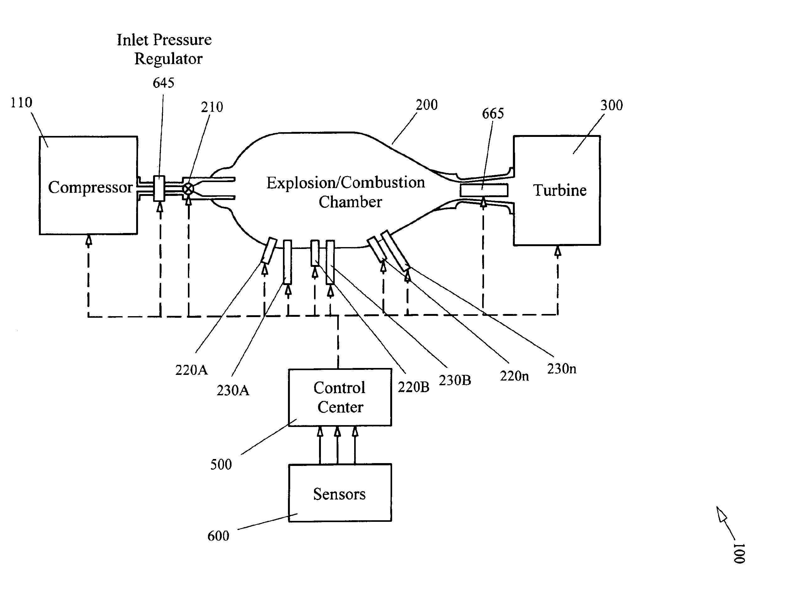
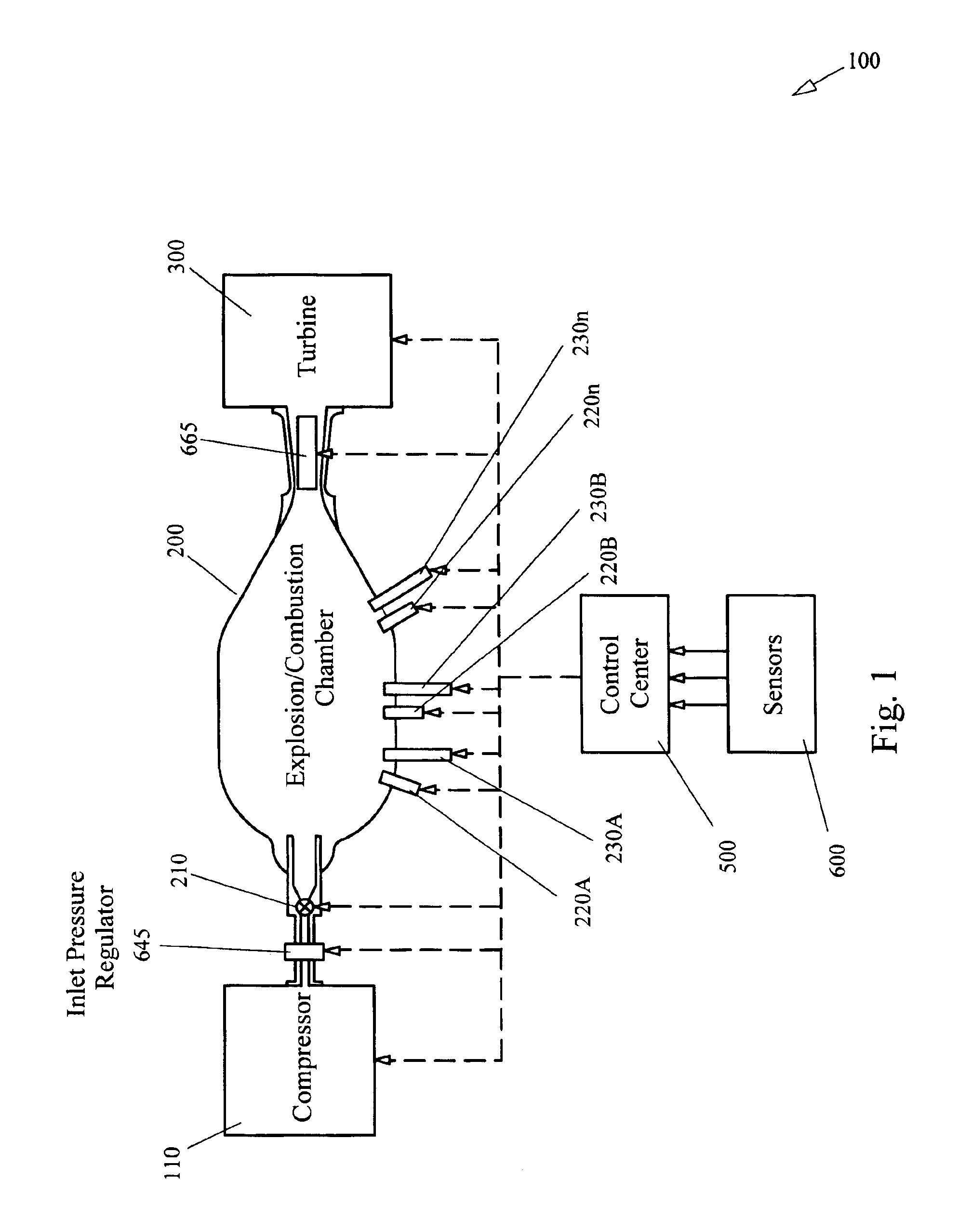
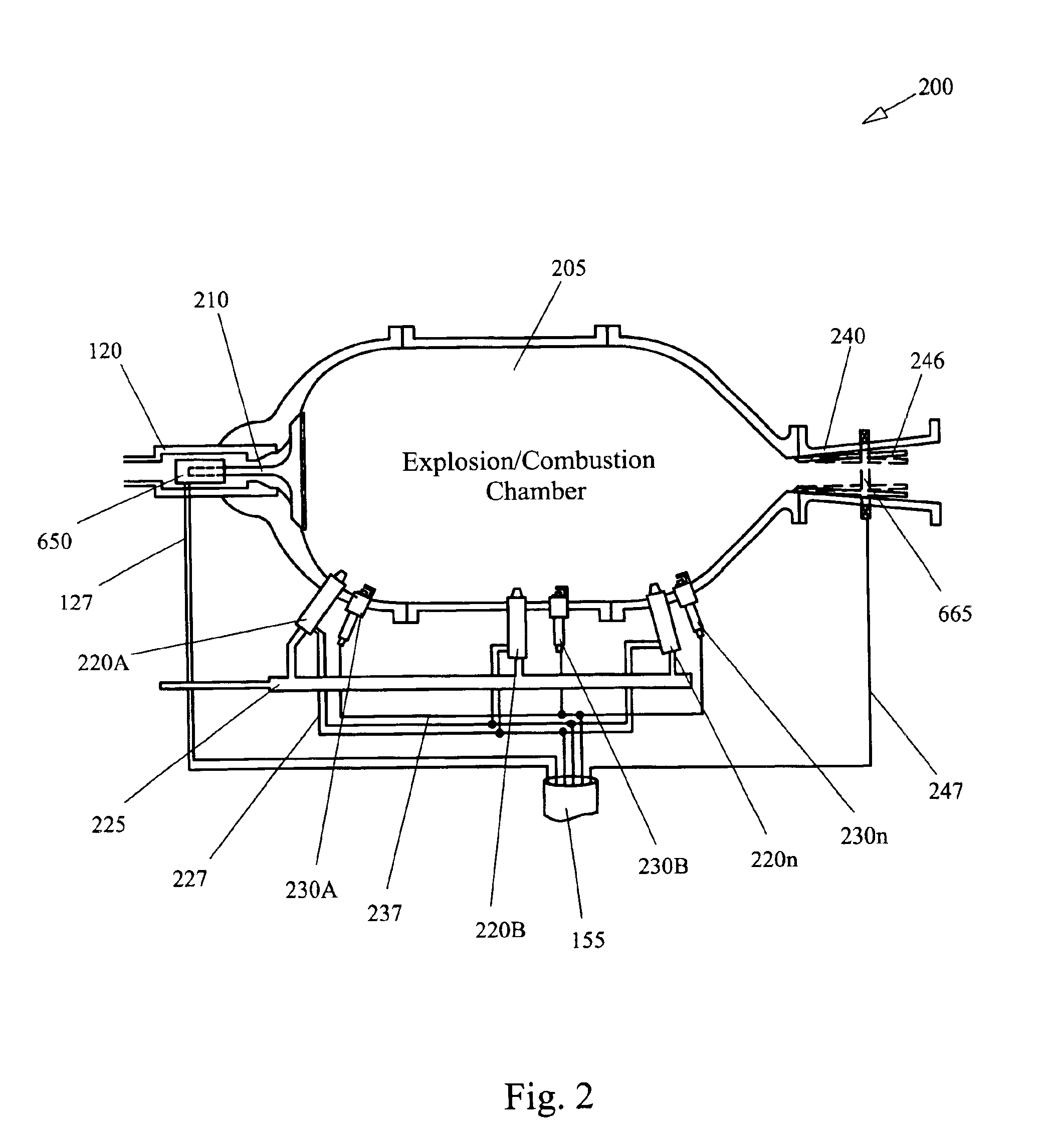
[0028]As described briefly above, the present invention combines operational aspects of both internal combustion and jet engine technologies to provide an economical, low hydrocarbon emissions power plant useful for a broad range of applications. FIG. 1 provides an overall power generating system 100 typical of that which could be used in conjunction with the present invention. Note that this system is exemplary only, thus no limitation is implied by the diagram. For example, while the exemplary system shown is driving a turbine to produce electricity, the present invention could just as easily be coupled to a drive shaft mechanism for propelling a vehicle. For the remainder of the detailed discussion the system of FIG. 1 will be used, however, it will be understood that the discussion of the present invention applies to any power plant application based upon the method and apparatus of the present invention.

[0029]A compressor 110, driven by electrical or mechanical feedback means, ...


PUM


Abstract

The method and apparatus of the present invention discloses a power plant operating at low inlet pressure and temperature using a combination of conventional internal combustion engine techniques and jet engine techniques. The combination of a unique combustion chamber design, a novel variable impedance blade set turbine and a closed loop control system allows a variable resonant frequency for combusted gases. As the resonant frequency is approached a control mechanism uses sensor data to maintain the operating point such that maximum power output is achieved for a given throttle setting. The combination of the unique combustion chamber design, multiple fuel injector / sparking device pairs, finely atomized fuel, excess oxygen and the closed loop control system further provides a very linear power curve with low exit hydrocarbon pollution levels and high fuel efficiency.

Description

[0001]This non-provisional application is related to U.S. provisional patent application No. 60 / 437,765, filed on Jan. 3, 2003 and claims the earlier filing date thereof.BRIEF DESCRIPTION[0002]The subject of this invention relates to general purpose engines. Specifically, this invention concerns a novel combination of internal combustion and jet engine principles to provide a high efficiency, low hydrocarbon emission power plant suitable for a wide variety of purposes including motor vehicles, power generation, and aircraft engines among others.BACKGROUND OF THE INVENTION[0003]General purpose engines have been in use for well over a century. Early types included steam driven, hydro powered, and internal combustion powered engines that accomplished a myriad of tasks. Tasks such as milling, irrigation, and factory machine power were the first uses. The advent of the railroad saw steam powered engines that were powerful enough to pull very heavy loads for a relatively small physical si...

Claims


Application Information

Patent Timeline
Patent Type & Authority Patents(United States)
IPC IPC(8): F02C5/02F02C9/00F02C5/00
CPCF02C5/02F02C9/00F23R7/00
Inventor LAPER, DENNIS A.
Owner LAPER DENNIS A
Learn More