Method of estimating engine lubricant condition

a technology of engine lubricant and condition estimation, which is applied in the direction of instruments, structural/machine measurement, transportation and packaging, etc., can solve the problems of high frequency maintenance, short useful life of lubricating oil, and high cost of changing lubricating oil. , to achieve the effect of reducing the cost of changing lubricating oil

Inactive Publication Date: 2005-07-26
INT TRUCK INTPROP LLC
View PDF11 Cites 73 Cited by
  • Summary
  • Abstract
  • Description
  • Claims
  • Application Information

AI Technical Summary

Problems solved by technology

While cost effective fleet management and readiness requirements demand the practice of preventive maintenance, one aspect of preventive maintenance, the engine lubricating oil change interval, has often been conservatively biased based on an assumption that the vehicle has been exposed to severe service and that the lubricating oil is thus likely to have a short useful life.
Changing lubricating oil costs money and removes a vehicle from service for a period of time.
Increased vehicle down time may compel an operator to have more tractors in a fleet than would otherwise be necessary and high frequency maintenance complicates fleet scheduling.
While changes of lubricating oil extend the service life of a vehicle they are economically productive only up to a point, and become wasteful and uneconomic if done excessively often.
Changes of engine lubricating oil are necessitated by the fact that lubricating oil deteriorates with use.
With degradation of the quality of lubricating oil, an engine is exposed to unnecessary wear and corrosion.
Soot becomes an issue in engine oil when the amount of soot overwhelms dispersants in the oil and begins to agglomerate.
The transfer of soot from a cylinder to the engine oil varies with a number factors, such as the use of low volatility diesel fuel blends at low ambient temperatures or operation of the engine at a disadvantageous point on the engine torque curve.
However, heavy soot loading of the oil stems primarily from high engine loads over extended periods of time.
High loads result in increased cylinder blow-by Which adds soot to the oil at a greater rate and which produces localized high temperatures in the oil leading to molecular degradation.
However, BMEP is currently difficult and expensive to measure in real time engine applications.
Other products are produced in the combustion process which infiltrate into the lubricating oil and progressively degrade its performance.
Once in the oil these compounds, particularly H2SO4, dissolve in any water they encounter and form a highly corrosive acid which attacks engine components.
Other factors are known to contribute to early oil degradation, particularly if engine duty cycles are of short duration.
Water can contaminate engine oil from moisture bearing air entering through the oil filler nozzle or from the engine cooling system.
As discussed above, water combines with the sulfur compound combustion by-products discussed above to form highly corrosive acids in the engine oil and thereby exposing an engine to corrosion damage.
Another possible engine contaminant is ethylene glycol, which can escape from the engine coolant system.
Fuel contamination is also a possibility.
Both of these contaminants reduce the lubricity of engine oil.
Existing sensors typically provide for measuring a variety of engine operating variables and while they indicate the conditions encountered by the oil they do not usually provide a direct indication of the condition of the oil.

Method used


Image

  • Method of estimating engine lubricant condition
  • Method of estimating engine lubricant condition
  • Method of estimating engine lubricant condition

Examples


Embodiment Construction

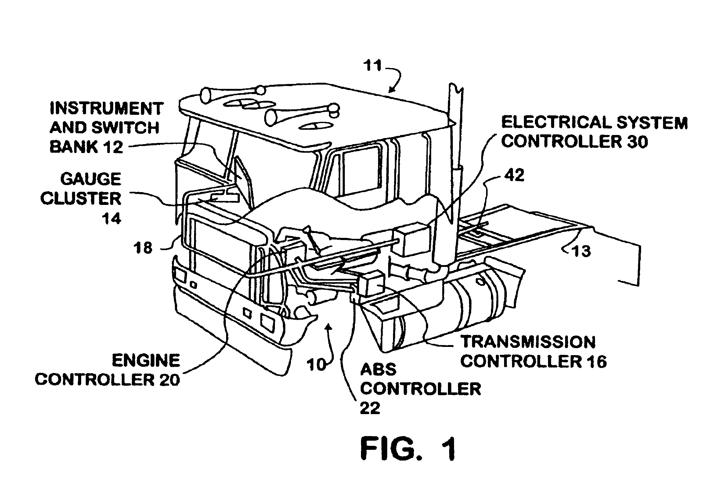
[0030]Referring now to the figures and more particularly to FIG. 1, a perspective view illustrates a vehicle 11 and an electrical control system 10 installed on the vehicle. Vehicle electrical system 10 comprises a twisted pair (either shielded or unshielded) cable operating as a serial data bus 18. One node of bus 18 is an electrical system controller (ESC) 30, which is a higher level data processing component of electrical control system 10. ESC 30 manages a number of vocational controllers connected to bus 18 as nodes and disposed on vehicle 11. Preferably, bus 18 and the various nodes attached thereto form a controller area network (CAN).

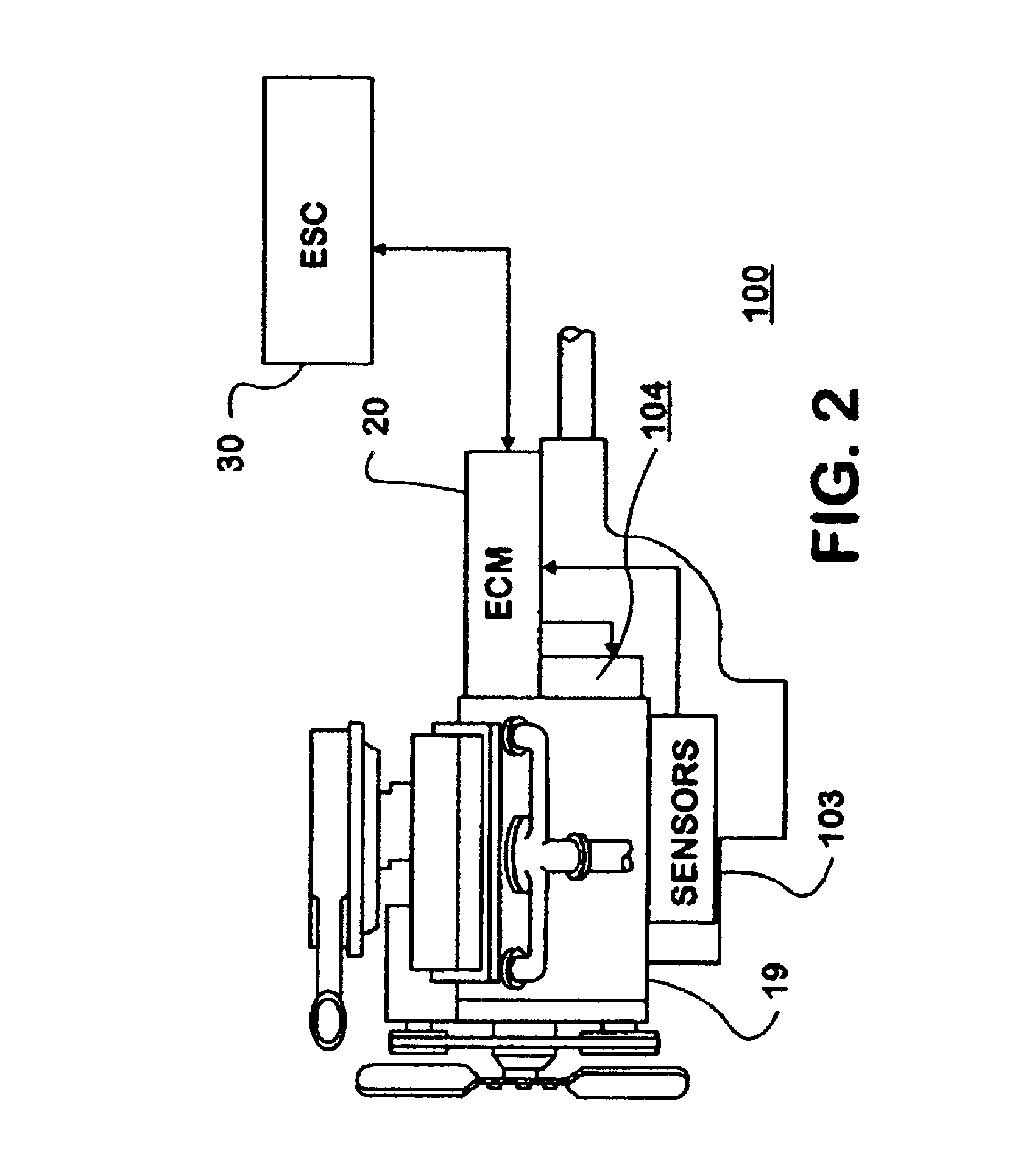
[0031]Active vehicle components are typically controlled by one of a group of autonomous, vocational controllers, which include a gauge cluster 14, an engine controller 20, which is typically supplied with an engine 19 (shown in FIG. 2), a transmission controller 16, an auxiliary instrument and switch bank 12, and an antilock brake system (ABS) ...


PUM

PropertyMeasurementUnit
timeaaaaaaaaaa
distanceaaaaaaaaaa
temperatureaaaaaaaaaa

Abstract

A motor vehicle having an internal combustion engine and a lubricating oil circulation system provides estimates of the distance remaining before an oil change becomes imperative. An indirect estimate of the depletion of various additives and the deterioration of oil operating characteristics is based on engine operating variables including oil temperature, ignition timing and engine load. The limit of depletion of total base number is dynamic, since it is set against total acid number and the two figures are independently calculated.

Description

BACKGROUND OF THE INVENTION[0001]1. Field of the Invention[0002]The present invention relates generally to a method for estimating the condition of engine lubricating oil in situ, and more particularly to a method of monitoring engine operating variables for predicting economically optimal oil change intervals.[0003]2. Description of the Prior Art[0004]Truck fleet operation is highly competitive and fleet operators are highly conscious of the need to balance preventive maintenance costs, repair costs, fleet operational availability and vehicle replacement costs. While cost effective fleet management and readiness requirements demand the practice of preventive maintenance, one aspect of preventive maintenance, the engine lubricating oil change interval, has often been conservatively biased based on an assumption that the vehicle has been exposed to severe service and that the lubricating oil is thus likely to have a short useful life. Changing lubricating oil costs money and removes ...

Claims


Application Information

Patent Timeline
Patent Type & Authority Patents(United States)
IPC IPC(8): G01N33/28G01N33/26
CPCG01N33/2876
Inventor CARLSTROM, KEVIN R.LARSON, GERALD L.BONDAROWICZ, FRANK
Owner INT TRUCK INTPROP LLC
Why Eureka
Try Eureka