Fabrication of Zinc Oxide films on non-planar substrates and the use thereof

a technology of zinc oxide film and non-planar substrate, which is applied in the direction of instruments, cladded optical fibres, optical elements, etc., can solve the problems of undesirable effect on device performance, limited maximum achievable efficiency and phase modulation of devices previously constructed, and the non-negligible conductivity of deposited films as the most important limiting factor in these devices, so as to improve phase modulation characteristics, improve efficiency, and improve the effect of phase modulation

Inactive Publication Date: 2005-07-26
UNISEARCH LTD
View PDF12 Cites 4 Cited by
  • Summary
  • Abstract
  • Description
  • Claims
  • Application Information

AI Technical Summary

Benefits of technology

[0012]It has been found in practice that, through the utilisation of chemical vapour deposition techniques, acusto-optical phase modulators having higher levels of efficiency, in excess of 0.25 radiums / √MW / cms, can be constructed. Further, phase modulators utilising the aforementioned techniques have been found to have substantially higher phase modulation capabilities than previously possible. This allows for their incorporation in interferometric optic arrangements which have improved phase modulation characteristics.

Problems solved by technology

The devices previously constructed have had limited maximum attainable efficiency and phase modulation.
This was found to have an undesirable affect on device performance.
Further, the most important limiting factor in these devices appears to be the non-negligible conductivity of the deposited films.

Method used


Image

  • Fabrication of Zinc Oxide films on non-planar substrates and the use thereof
  • Fabrication of Zinc Oxide films on non-planar substrates and the use thereof
  • Fabrication of Zinc Oxide films on non-planar substrates and the use thereof

Examples


Embodiment Construction

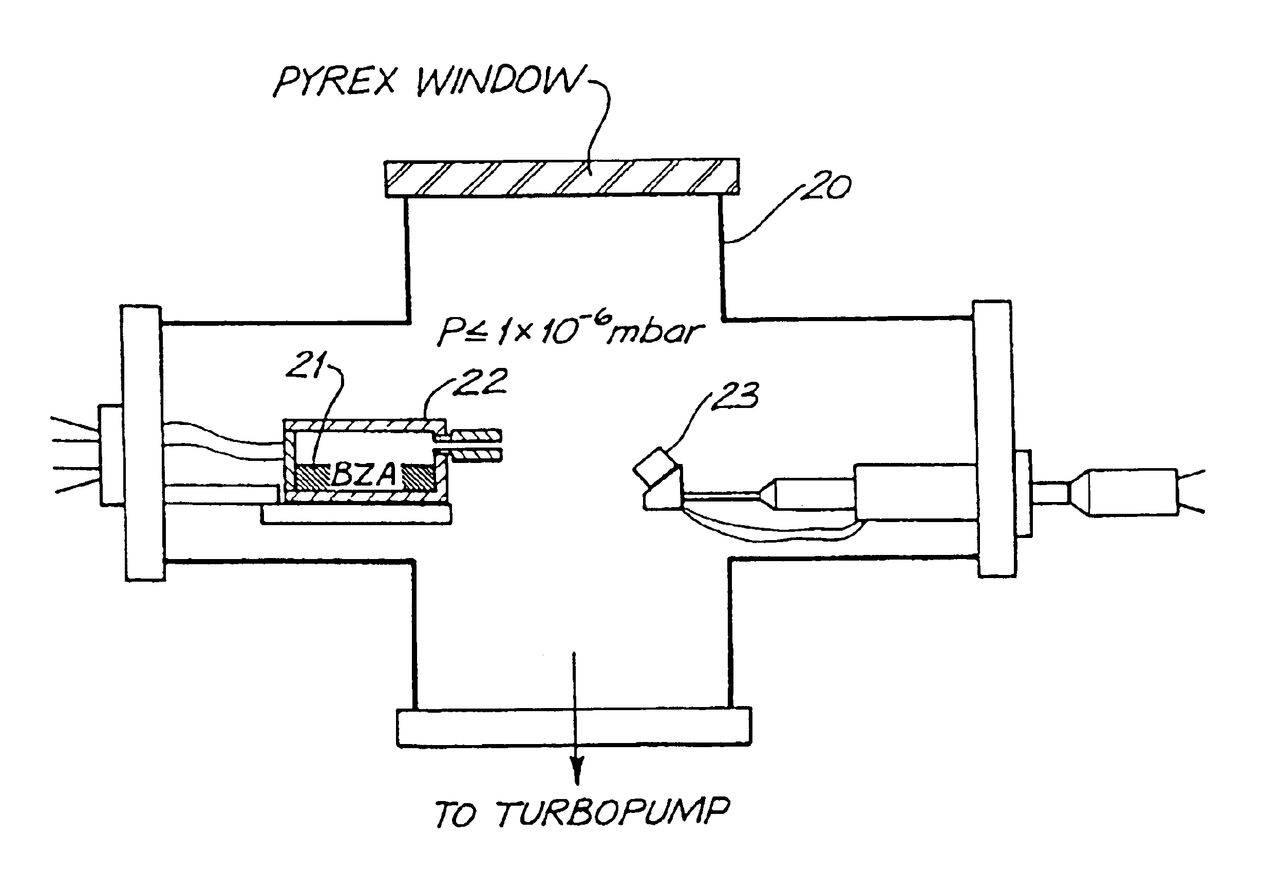
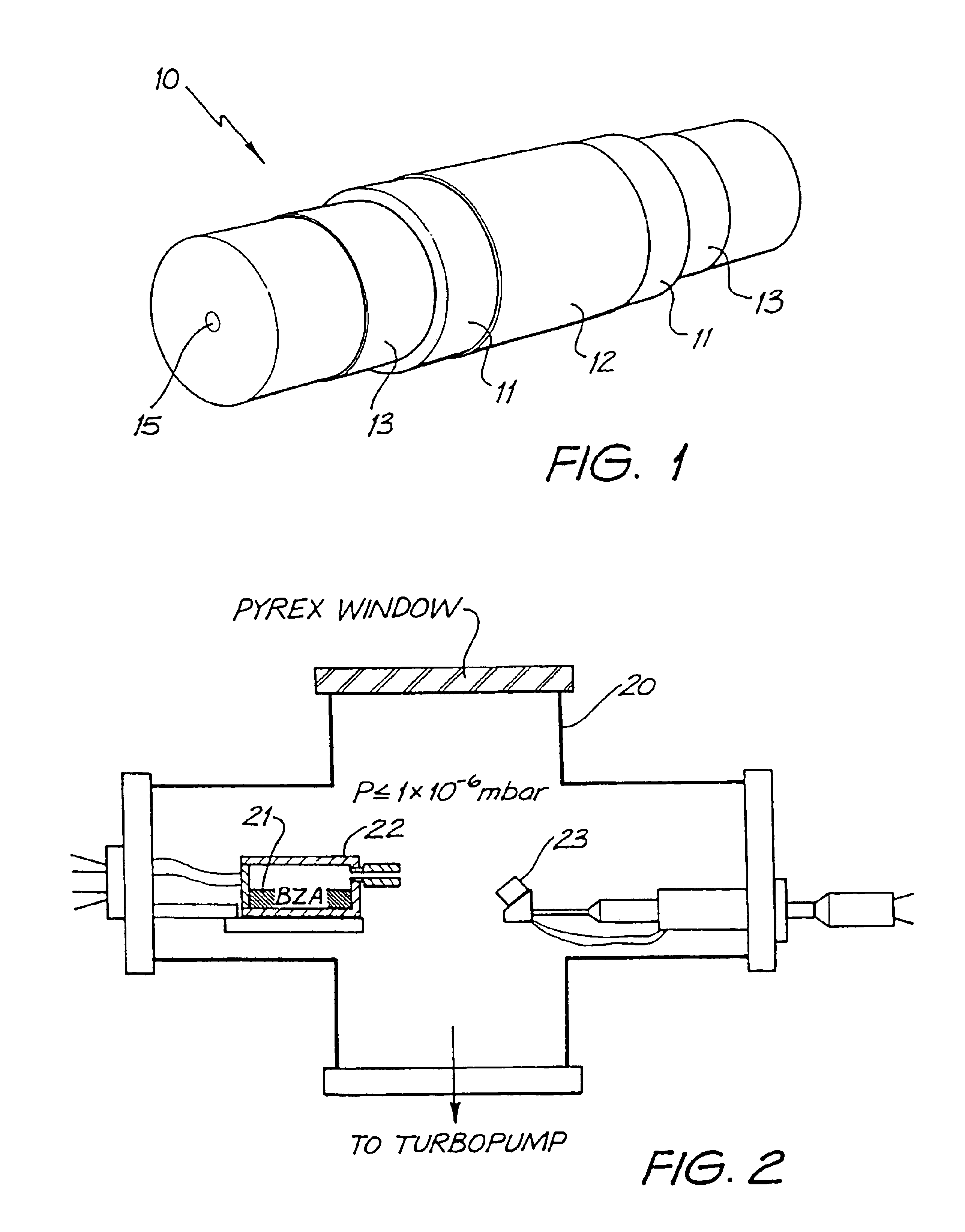
[0025]In the preferred embodiment, an all-fibre acousto-optic phase modulator was produced using a ZnO film deposited by a modified single source chemical vapour deposition (SSCVD) process from a metal-organic precursor. The precursor used was Zn4O(CH3C00)6 (basic zinc acetate, BZA).

[0026]In FIG. 2, there is illustrated a schematic of the high vacuum chamber 20 utilized to construct the modulator. The films were deposited in a high vacuum (P≦1×10⁻⁶ mbar), and the BZA precursor 21 was vapourised in a modified Knudsen cell 22 by resistively heating the cell. FIG. 11a to 11c illustrate various views of the modified two zone Knudsen cell which includes a reservoir 110 formed via a screw in stopper 111, an outer cell 112 and a series of bores 114 for the receipt of ceramic insulated Ta resistance wires for heating. Also provided is an exit aperture 115 for the exit of materials.

[0027]The cell temperature was adjusted so that the partial pressure of BZA in the chamber 20 was approximately...


PUM

PropertyMeasurementUnit
thicknessesaaaaaaaaaa
frequencyaaaaaaaaaa

Abstract

A method of manufacture of a substantially continuous circumferential coating on a non-planar substrate, is disclosed the method comprising the steps of: utilising a substantially non directional deposition technique and a substantially static substrate deposition geometry to deposit the coating. Coatings can be deposited which include piezoelectric modulation characteristics or electro-optic modulation characteristics. Ideally the coating has semiconducting properties. The type of coating ideally includes Zinc-Oxide coatings. The non directional deposition technique can comprise chemical vapor deposition via single source chemical vapor deposition. Suitable substrates include optical fibers which are clamped onto a substantially planar heating surface during the deposition. The optical fiber can be clamped at a portion of the length of the fiber which is located at one end of a heating surface during the deposition such that movement of a free end of the optical fiber is limited to movement substantially along the axis of the optical fiber.

Description

FIELD OF THE INVENTION[0001]The present invention relates to the fabrication of Zinc Oxide films on non-planar substrates such as optical fibres and their use in devices such as piezo-electric or electro optic modulators.BACKGROUND OF THE INVENTION[0002]Recently, there has been a growing interest in the development of thin film piezo-electric materials for use in all fibre acousto-optic modulators. In FIG. 1 there is illustrated a schematic representation of the typical modulator device structure 10 where a film of active material 11 (typical thickness from 5 to several 10's of μm) is sandwiched between two electrical contact layers 12, 13 (thicknesses up to 1 μm) covering a full 360° surface of a fibre. The cylindrical geometry of such devices 10 results in highly efficient polarisation independent modulators as the acoustic waves are focussed at the fibre core 15.[0003]The active material 11 can be Zinc Oxide (ZnO) which is a II-VI semiconductor with strong piezo-electric and elec...

Claims


Application Information

Patent Timeline
Patent Type & Authority Patents(United States)
IPC IPC(8): C03C25/12C03C25/22C03C25/10C03C25/42G02B6/44G02F1/01G02F1/055
CPCC03C25/107C03C25/223C03C25/1061
Inventor KOCH, MICHAEL HERMANLAMB, ROBERT NORMANMAR, GOCK LEONGTIMBRELL, PETER YORKE
Owner UNISEARCH LTD
Why Eureka
Try Eureka