Fuel hose and producing method therefor

a technology of fuel hoses and hoses, which is applied in the direction of other domestic products, synthetic resin layered products, chemical processes, etc., can solve the problem that the longitudinal direction of the innermost layer cannot be blocked particularly at the end section, and achieve the effect of low fuel permeability and high fuel permeability

Inactive Publication Date: 2005-08-02
NISSAN MOTOR CO LTD
View PDF14 Cites 12 Cited by
  • Summary
  • Abstract
  • Description
  • Claims
  • Application Information

AI Technical Summary

Benefits of technology

[0003]In the above fuel hose, the innermost layer is formed of the rubber for the purpose of securing the sealing ability to the connection-partner pipe which is to be fitted into the opening of an end section of the fuel pipe. In this case, even if the innermost layer is formed of fluororubber which is lower in fuel permeability in rubbers, the rubber is very high in fuel permeabilit

Problems solved by technology

Consequently, in the above conventional fuel hose, fuel permeation in a direction of thickness (radial direction) can be blocked by the intermediate

Method used


Image

  • Fuel hose and producing method therefor
  • Fuel hose and producing method therefor

Examples


example 1

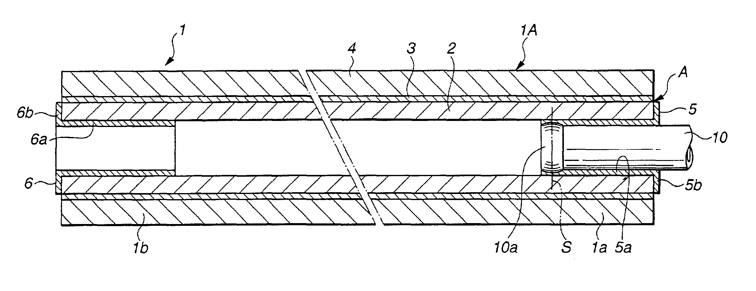
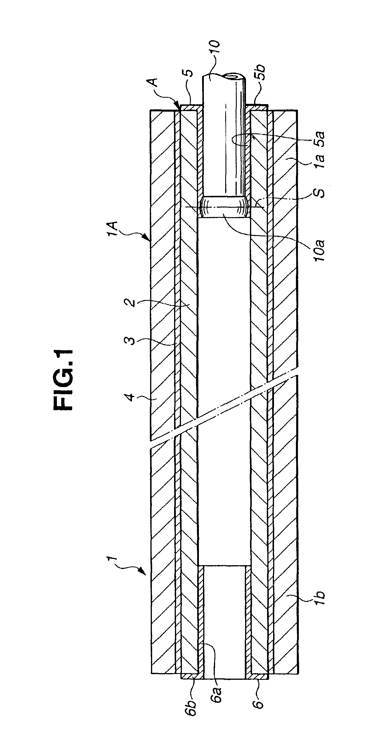
[0032]Amine-based primer was coated at the opposite end regions of the inner peripheral surface of hose main body 1A and the opposite end faces of hose main body 1A, followed by drying. Each end region extended from the end face to a longitudinal position of 30 mm from the end face. The primer-coated surface of hose main body 1A was then coated with a solution which had been prepared by dissolving 15% by weight of powder of tetrafluoroethylene-hexafluoropropylene-vinylidene fluoride copolymer (“THV 220” produced by DYNEON) in methylethyl ketone (MEK). Then, the coated surface of hose main body 1A was subjected to drying at 40° C. for 30 minutes, followed by further drying at 100° C. for 30 minutes, thereby forming end covering material 5 made of tetrafluoroethylene-hexafluoropropylene-vinylidene fluoride copolymer (THV) as a film having a thickness of 0.1 mm, thus producing fuel hose 1 of this Example. The THV had a fuel permeability coefficient of simulated fuel (discussed after) a...

example 2

[0033]The opposite end regions of the inner peripheral surface of hose main body 1A and the opposite end faces of hose main body 1A in a state of having been not yet vulcanized were coated with a solution which had been prepared by dissolving 15% by weight of powder of tetrafluoroethylene-hexafluoropropylene-vinylidene fluoride copolymer (“THV 220” produced by DYNEON) in methylethyl ketone (MEK), by using a brush. Each end region extended from the end face to a longitudinal position of 30 mm from the end face. Then, the coated hose main body 1A was subjected to vulcanization under a condition of 150° C. for 30 minutes, thereby forming end covering material 5 as a film, thus producing fuel hose 1 of this Example. End covering material 5 had a thickness of 0.1 mm, and therefore had a value of the tensile elastic modulus×the thickness, of 20 MPa·mm.

example 3

[0034]Hose main body 1A was dipped in a mixture solution of aqueous solution of hydrogen peroxide and aqueous solution of formic acid in such a manner that the opposite end regions of the inner and outer peripheral surfaces of hose main body 1A and the opposite end faces of hose main body 1A were brought into contact with the mixture solution, at 60° C. for 10 minutes. Each end region extended from the end face to a longitudinal position of 30 mm from the end face. Then, the hose main body 1A was dried at room temperature thereby forming a modified surface portion at the opposite end regions of the inner peripheral surface of hose main body 1A and the opposite end faces of hose main body 1A, thus producing fuel hose 1 of this Example. The modified surface portion had a surface hardness of A80 measured by the type A durometer according to JIS K 6253.


PUM

PropertyMeasurementUnit
Thicknessaaaaaaaaaa
Permeabilityaaaaaaaaaa
Elastic modulusaaaaaaaaaa

Abstract

A fuel hose for an automotive vehicle has an end section to which a connection-partner member is to be fitted. The fuel hose comprises an innermost layer formed of rubber or synthetic resin. The innermost layer has an inner surface defining an opening through which fuel flows and has an end section corresponding to the end section of the fuel hose. An outer layer is formed outside the innermost layer and formed of a material lower in fuel permeability coefficient than the innermost layer. Additionally, an end covering material is formed covering a surface region of the innermost layer which surface region includes the inner surface at a part extending from a sealing position to an end face of the innermost layer and the end face of the innermost layer. The end covering material is lower in fuel permeability coefficient than the innermost layer.

Description

BACKGROUND OF THE INVENTION[0001]This invention relates to improvements in a fuel hose to be used for an automotive vehicle or the like, and in a method of producing the fuel hose, and more particularly to the improvements in the fuel hose to be used in an evaporative emission control system.[0002]In general, fuel hoses for an automotive vehicle take a multiple layer structure including layers formed of rubber and synthetic resins excellent in fuel permeation resistance in order to prevent emission of fuel vapor. An example of such fuel hoses is disclosed in Japanese Patent Provisional Publication No. 8-108499 and has a three layer structure including an innermost layer, a intermediate layer and an outermost layer. The innermost layer is formed of an elastomeric material such as acrylonitrile-butadiene copolymer rubber (NBR) or fluororubber (FKR) in order to ensure the sealing ability to a connection-partner pipe and the pull-out force of the fuel hose. The intermediate layer is for...

Claims


Application Information

Patent Timeline
IPC IPC(8): B29C65/48B29C70/00B29C70/76F16L11/04B29C41/20B29C41/02B29C37/00B32B1/08B32B27/00C09K3/10
CPCB29C66/534B29C70/766F16L11/045B29C66/5344B29C65/4835B29C37/0078B29C41/20B29L2009/00Y10T428/1393F16L2011/047B29L2023/005B29C65/1406B29C66/1222B29C66/1224B29C66/131B29C66/612B29C66/71B29C66/7234B29K2077/00B29K2067/00B29K2033/08B29K2027/12B29K2027/06B29K2021/003B29K2021/00
Inventor KUMAGAI, HIROSHIMOROHOSHI, KATSUMIYAMADA, MITSUOHONMA, MASAMI
Owner NISSAN MOTOR CO LTD
Why Eureka
Try Eureka