Intravascular stent

a technology of intravascular stents and stents, which is applied in the field of intravascular implants, can solve the problems of considerable complexity of procedures, blood coagulation and possible thrombosis, and some turbulence in flow, and achieves low profile, small frontal area, and low memory level.

Inactive Publication Date: 2005-08-02
MEDTRONIC INC
View PDF202 Cites 123 Cited by
  • Summary
  • Abstract
  • Description
  • Claims
  • Application Information

AI Technical Summary

Benefits of technology

[0027]The improvement of this invention over other similar devices such as cited in patents above, and specifically my previus invention described in U.S. Pat. No. 4,649,992, is the ability of the device of this invention to allow for and to maintain a very low profile and a small frontal area, so very important for purposes of percutaneous insertion. Thus the stent of this invention can be inserted into and be transported via a standard #8F Guiding Catheter such as USCI Cat. #006128, while using standard procedures and methods. Once on location, the stent can be expanded radially to a diameter larger than initially introduced; a ratio of =2½:1 can easily be achieved with a wire diameter of 0.008 and initial stent diameter of 0.075. The expanded larger diameter will conform to the inside of the vessel and maintain intimate contact with the inside wall. The stent of this invention is characterized by the low memory level of the relatively easily deformable metal used for the wire.

Problems solved by technology

One and foremost is the fact that the spring has a fixed diameter and as such is unable to fully conform to the inside wall of the vessel which at times is quite tortuous and thus could conceivably create a somewhat turbulant flow of blood, and possible thrombosis could in some cases result.
All of the above mentioned devices present drawbacks of various magnitudes including blood coagulation and possible thrombosis and considerable complexity of procedure.
Also, for the repair of the most difficult and most dangerous dissection, namely the type I which is that of the ascending aorta and the aortic arch, no stent is available today which could be used and be implanted intraluminarely for non-surgical repair of such a dissection.
Most intravascular prosthesis and stent available today are of limited length and diameter and are especially limited in terms of flexibility and more specifically in terms of longitudinal flexibility unable to conform to tight bends and adhere to the walls of the intima and at the same time be flexible to stretch and move with each heartbeat such as experienced in the aortic arch.
Surgical procedures of this type involve high risk to the patient, a highly skilled team of cardiovascular surgeons and sophisticated equipment, because it requires the replacement of the affected region with an interpositional graft.
High mortality and morbidity are associated with surgery in this region.
This is especially true for the elderly and other poor candidates for a major surgery.
The cost associated with such a surgical procedure is also very high.

Method used


Image

  • Intravascular stent
  • Intravascular stent
  • Intravascular stent

Examples


Embodiment Construction

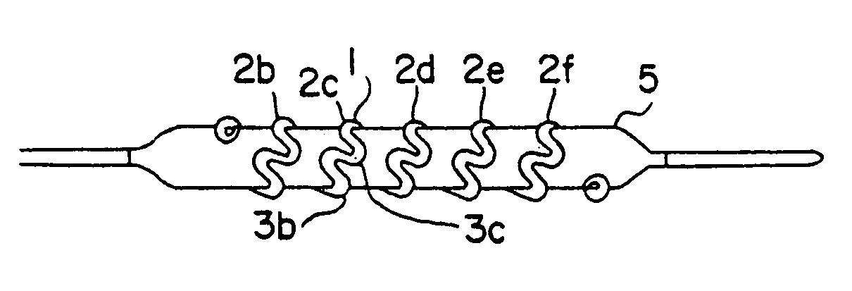
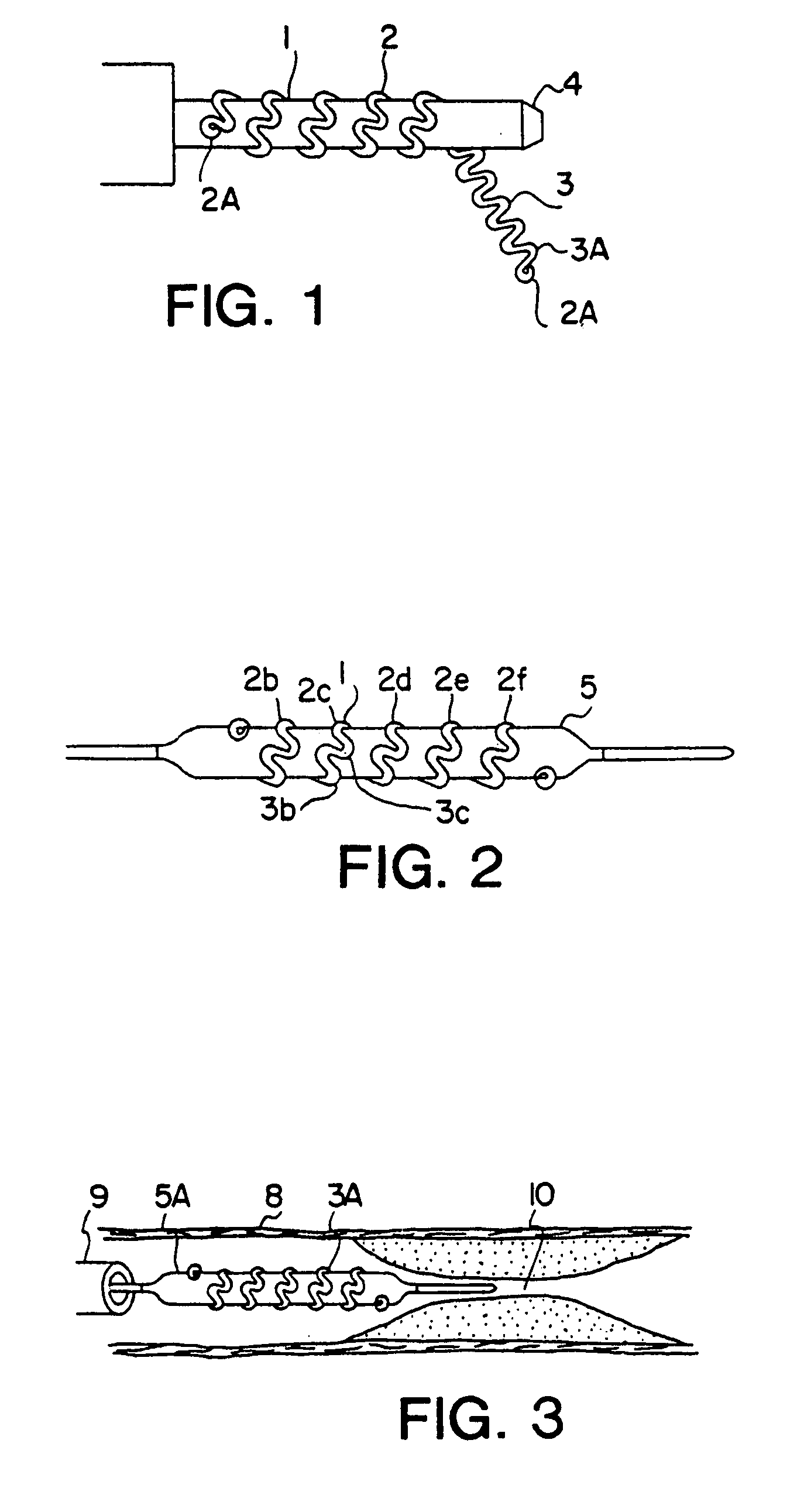
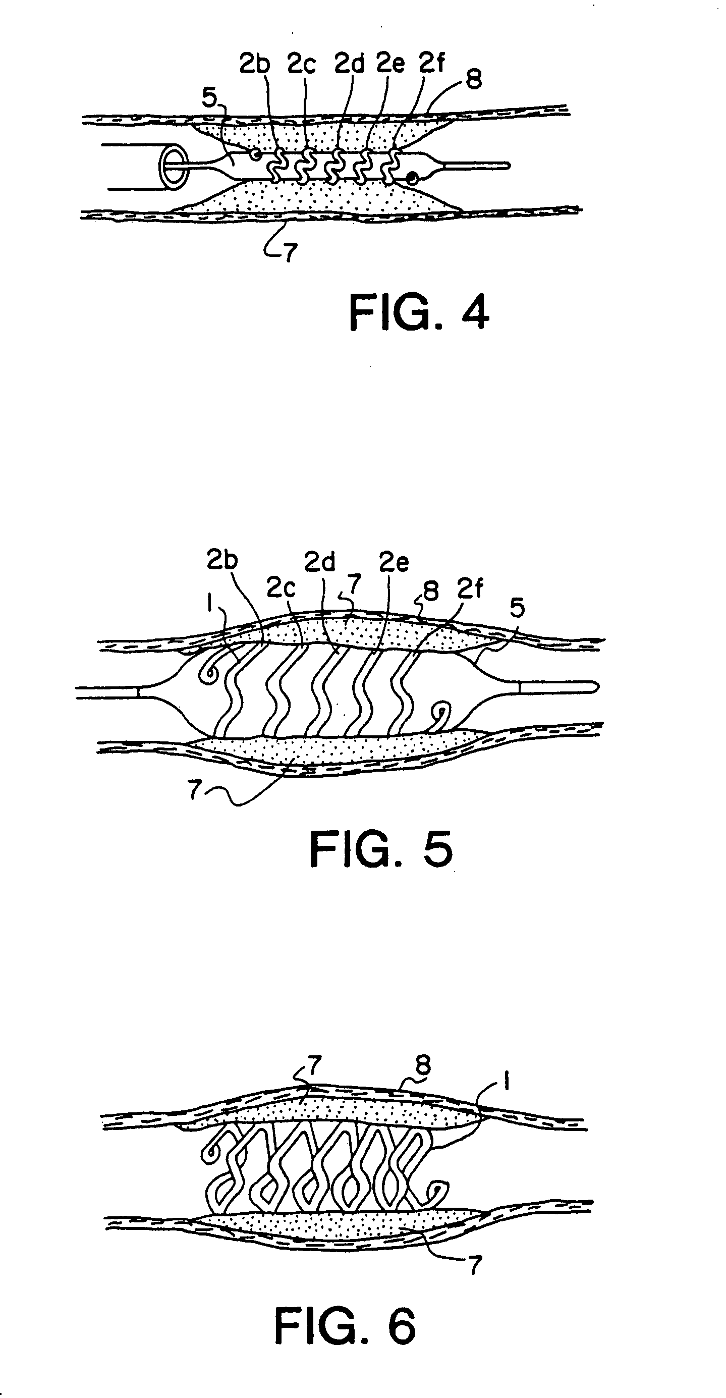
[0049]For purposes of better and clearer understanding of this invention, reference is made to FIGS. 1–6. The preferred embodiment of this invention is shown and described in an application for angioplasty; however, it is understood that other applications not specifically mentioned herein are ossible and no limitations in scope of this invention are intended or implied without departing from the basic principles of this invention.

[0050]FIG. 1 shows the details of construction of the prosthesis stent 1, hereafter called stent, which is basically of a hollow open-ended cylindrical shape. Stent 1 is basically a tubular shape of coiled preformed wire band typically wound on a suitable mandrel 4. The wire is made of drawn low-memory level material such as stainless steel, titanium ASTM F63-83 Grade 1 or high carat gold K 19–22. Copper alloy typically 110 when properly coated with polyester or Teflon® can also be used. Titanium and gold are biologically compatible and inert and requires ...


PUM


Abstract

A medical device for use in the interior of a body lumen includes a balloon catheter and a radially expandable stent. The stent includes a plurality of zig-zags of a low memory metal formed into a hollow, open-ended cylindrical shape. The individual zig-zags have a curved portion forming a reversing bend which allows the zig-zags to expand and deform as the balloon radially expands the stent. The curved portions of the zig-zags are aligned along the length of the stent in a spaced-apart arrangement with some curved portions attached and others unattached to adjacent zig-zags. The resulting stent is longitudinally flexible throughout its length when unexpanded and is also capable of conforming to a bend in the body lumen when expanded.

Description

CROSS REFERENCE TO RELATED APPLICATIONS[0001]This is a continuation of Ser. No. 09 / 531,097 filed Mar. 21, 2000, now abandoned, which in turn is a continuation of Ser. No. 07 / 872,737 filed Apr. 22, 1992, now U.S. Pat. No. 6,113,621, which in turn is a continuation of Ser. No. 07 / 327,286 filed Mar. 22, 1989, now U.S. Pat. No. 5,133,732, which in turn is a continuation-in-part of Ser. No. 07 / 109,686 filed Oct. 19, 1987, now U.S. Pat. No. 4,886,062.FIELD OF THE INVENTION[0002]This invention relates to intravascular implants for maintaining vascular patency in humans and animals. The present invention comprises an open-ended wire formed device of basically cylinrical shape and made of a softer-then spring type metal and fitted over an inflatable element of a typical balloon type catheter such as described in U.S. Pat. No. 4,195,637 and U.S. Pat. No. 4,402,307. The wire formed device is intended to act as a permanent prosthesis stent and is implanted transluminarely. Specifically, this in...

Claims


Application Information

Patent Timeline
Patent Type & Authority Patents(United States)
IPC IPC(8): A61F2/06A61F2/00A61F2/82A61F2/88A61F2/90
CPCA61F2/88A61F2/90B21F45/008A61F2/958A61F2002/825A61F2310/00017A61F2310/00023A61F2310/00077A61F2310/00155
Inventor WIKTOR, DOMINIK M.
Owner MEDTRONIC INC
Why Eureka
Try Eureka