Lithographic apparatus, device manufacturing method, and device manufactured thereby

a technology of lithographic apparatus and manufacturing method, which is applied in the direction of x-ray tubes with very high current, radiation therapy, photometry, etc., can solve the problems of unacceptably high significantly more sensitive apparatus operating at such wavelengths to the presence of contaminant particles, and loss of radiation beam transmission. , to achieve the effect of reducing oxidative damag

Inactive Publication Date: 2005-08-02
ASML NETHERLANDS BV
View PDF14 Cites 13 Cited by
  • Summary
  • Abstract
  • Description
  • Claims
  • Application Information

AI Technical Summary

Benefits of technology

[0020]One aspect of embodiments of the present invention provides a lithographic projection apparatus comprising means capable of removing contaminant particles from the optical components. Another aspect of embodiments provides a method of reducing the oxidative damage caused to mirrors in EUV systems.

Problems solved by technology

However, apparatus which operate at such wavelengths are significantly more sensitive to the presence of contaminant particles than those operating at higher wavelengths.
These contaminants tend to adsorb to the optical components in the system and cause a loss in transmission of the radiation beam.
Such a loss in transmission is unacceptably high.
Localized contamination can cause this requirement not to be met.
There is also a risk that the adsorption of contaminant particles on the surface of the optical components, or within the optical surface in the case of a porous surface, e.g. an anti-reflection coating, may cause damage, for example cracking, to the optical components themselves.
Such damage can occur if the optical components are suddenly irradiated with UV radiation, for example 157 nm radiation, at full power.
The irradiation will cause rapid evaporation of the smaller contaminant particles, such as water molecules, which are trapped within said porous surface of the optical component, hence damaging the optical surface itself.
However, such cleaning methods are very harsh and may damage the optical component to be cleaned, particularly at its surface.
In particular, the mask, which generally comprises a Teflon® (PTFE)-based or other organic material, can be damaged by the use of such methods.
A further problem associated with apparatus for use with EUV radiation relates specifically to the presence of water molecules in the apparatus.
However, the presence of water in combination with EUV radiation has a tendency to cause oxidation of mirrors.
This is an irreversible and highly damaging process and leads to a very significant loss in mirror reflection.
Due to the restrictively high cost of replacing the mirrors, this ultimately leads to the operation of the lithographic tool with poor reflection levels and therefore a reduction in productivity.
The reduction in lifetime of the mirrors which also results is a further distinct economic disadvantage.
However, very few successful results in this area have so far been demonstrated.
No protective method has yet been found which can increase the lifetime of mirrors used in EUV systems to greater than 15 hours.

Method used


Image

  • Lithographic apparatus, device manufacturing method, and device manufactured thereby
  • Lithographic apparatus, device manufacturing method, and device manufactured thereby

Examples


embodiment 1

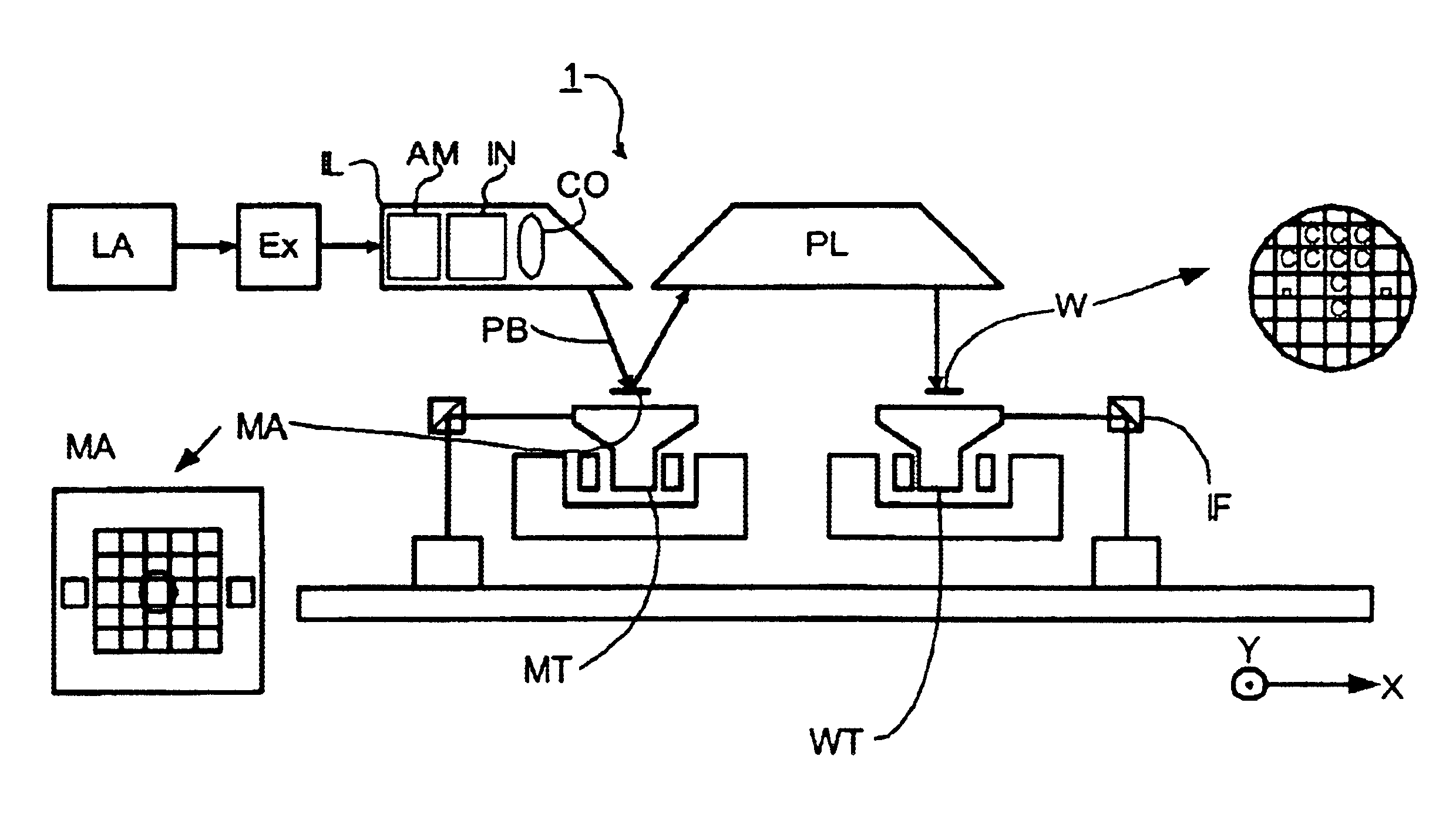
[0044]FIG. 1 schematically depicts a lithographic projection apparatus according to a particular embodiment of the invention. The apparatus comprises:[0045]a radiation system Ex, IL, for supplying a projection beam PB of radiation (e.g. UV or EUV radiation). In this particular case, the radiation system also comprises a radiation source LA;[0046]a first object table (mask table) MT provided with a mask holder for holding a mask MA (e.g. a reticle), and connected to first positioning means for accurately positioning the mask with respect to item PL;[0047]a second object table (substrate table) WT provided with a substrate holder for holding a substrate W (e.g. a resist-coated silicon wafer), and connected to second positioning means for accurately positioning the substrate with respect to item PL;[0048]a projection system (“lens”) PL (e.g. a mirror group) for imaging an irradiated portion of the mask MA onto a target portion C (e.g. comprising one or more dies) of the substrate W. As...

embodiment 2

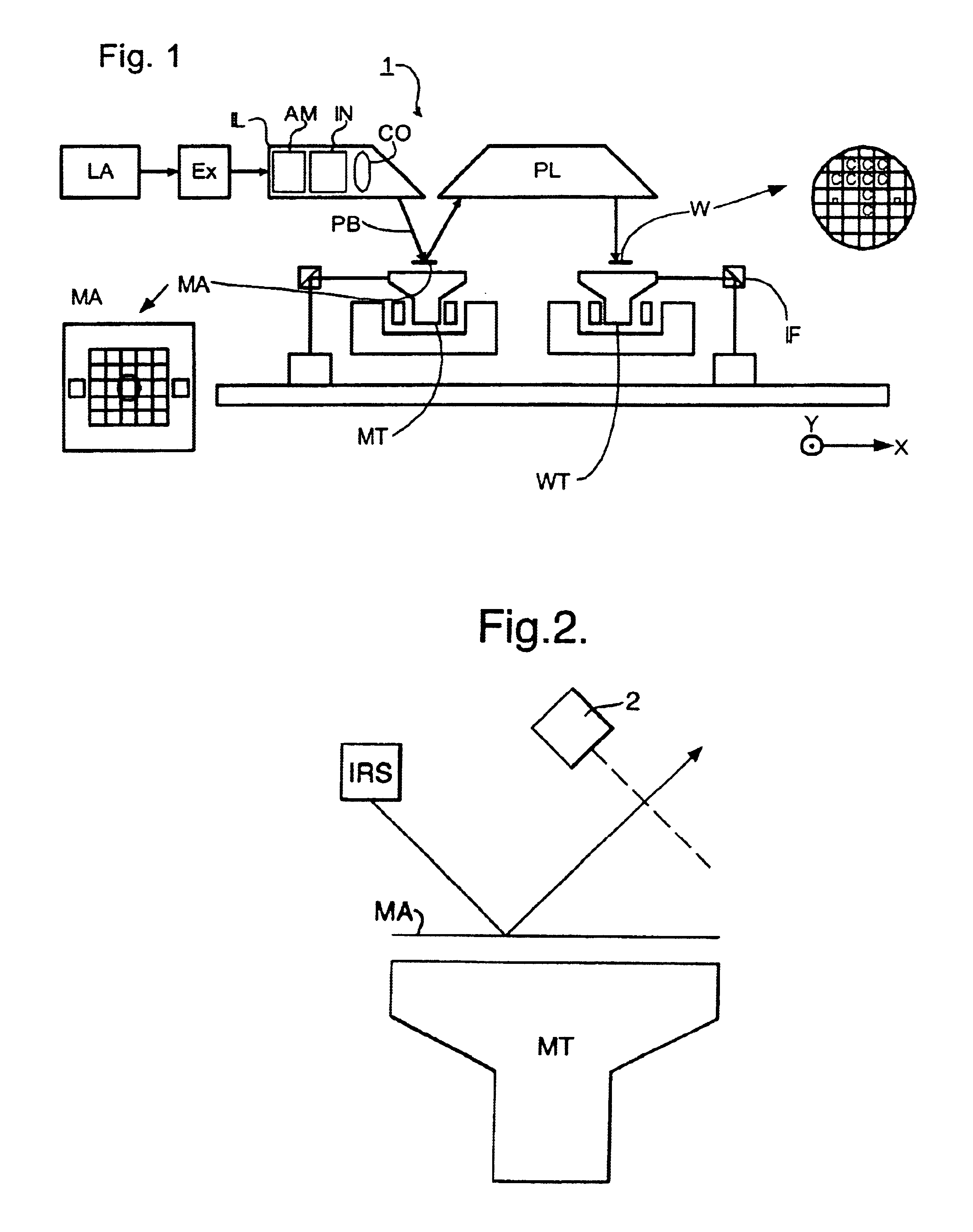
[0066]In a second embodiment of the invention, which is the same as the first embodiment, except as described below, the apparatus is fitted with a sensor 2 to monitor the absorption of the infra-red radiation by the contaminants on the surface of the optical components. As for embodiment 1, infra-red radiation has here been utilised, but it is also envisaged that microwave radiation may be used. In FIG. 2, sensor 2 is depicted as monitoring the absorption of infra-red radiation directed at the mask, but it may also be used to monitor absorption of radiation directed at any optical component.

[0067]As is depicted in FIG. 2, the optical component may be reflective, and the sensor will therefore measure the reflectance of the infra-red radiation. However, if the mask is of a transmissive type, the sensor will be positioned such that it measures the degree of transmission through the mask or other optical component.

[0068]The degree of absorption of the infra-red radiation indicates the ...

embodiment 3

[0071]In a third embodiment of the invention, which is the same as the first embodiment except as described below, the partial pressure of water in the system is reduced by irradiating with infra-red or microwave radiation, preferably infra-red radiation.

[0072]In this embodiment, the radiation system produces radiation in the extreme ultraviolet (EUV) range. For example, the radiation may have a wavelength below about 50 nm, preferably below about 20 nm and most preferably below about 15 nm. An example of a wavelength in the EUV region which is gaining considerable interest in the lithography industry is 13.5 nm, though there are also other promising wavelengths in this region, such as 11 nm, for example.

[0073]In this embodiment the interior of the lithographic apparatus is irradiated with IR light from IR source IRS. The frequency of the radiation is a frequency which is absorbed by water molecules. For example a frequency or a range of frequencies within the range of from 3500 cm−...


PUM

PropertyMeasurementUnit
wavelengthsaaaaaaaaaa
wavelengthaaaaaaaaaa

Abstract

Pre-cleaning or in situ cleaning of optical components for use in a lithographic projection apparatus can be carried out by irradiating the optical component with microwave and / or infra-red radiation, preferably infra-red radiation having a wavelength or a range of wavelengths in the range of from 1000 cm−1 to 4600 cm−1. This technique may be suitable for cleaning a mask. By monitoring the absorption of microwave and / or infra-red radiation directed at a contaminated optical component, the degree of contamination of said component can be qualified. This method may also be suitable for reducing the partial pressure of water in EUV apparatus.

Description

BACKGROUND OF THE INVENTION[0001]This application claims priority to EP 00311670.4 filed Dec. 22, 2000, herein incorporated by reference in its entirety.[0002]1. Field of the Invention[0003]The present invention relates generally to a lithographic projection apparatus and more particularly to lithographic projection apparatus including a contaminant removal system.[0004]2. Description of the Related Art[0005]Lithographic projection apparatus in accordance with the present invention generally include a radiation system for supplying a projection beam of radiation, a support structure for supporting patterning structure, the patterning structure serving to pattern the projection beam according to a desired pattern, a substrate table for holding a substrate, and a projection system for projecting the patterned beam onto a target portion of the substrate.[0006]The term “patterning structure” as here employed should be broadly interpreted as referring to means that can be used to endow a...

Claims


Application Information

Patent Timeline
Patent Type & Authority Patents(United States)
IPC IPC(8): G03F7/20H01L21/027
CPCG03F7/70925G03F7/20
Inventor VAN SCHAIK, WILLEM
Owner ASML NETHERLANDS BV
Why Eureka
Try Eureka