Method and apparatus for controlling power to a heater element using dual pulse width modulation control

a technology of pulse width modulation and control method, which is applied in the direction of electrographic process, instruments, transportation and packaging, etc., can solve the problems of difficult operation of the heater element, difficult operation within a narrow temperature window, and design constraints, so as to improve the warm-up characteristics and improve the temperature control

Inactive Publication Date: 2005-08-09
LEXMARK INT INC
View PDF11 Cites 31 Cited by
  • Summary
  • Abstract
  • Description
  • Claims
  • Application Information

AI Technical Summary

Benefits of technology

[0010]A method of controlling power applied to an electrical load is provided by the present invention whereby the application of power meets European harmonic and flicker requirements. In particular, the present invention provides a power control method which is adapted to be used for supplying power to a fuser having a high power heater element, and operates to provide improved warm-up characteristics, as well as improved temperature control maintaining an operating temperature of the fuser within a narrow temperature window.

Problems solved by technology

These requirements impose conflicting design constraints on a heater element incorporated within a heated fuser roll.
On the other hand, when controlling power to such a high power heater element, it is difficult to operate within a narrow temperature window, particularly when small, controlled temperature corrections are required to maintain a target temperature.
A further limitation on the operation of the heater element relates to noise reduction requirements imposed in Europe on all electrical and electronic equipment, known as the “harmonic” requirement IEC 61000-3-2, and the “flicker” requirement IEC 61000-3-3.
When power is first applied to the heater element for the fuser, such as a 750 W tungsten-filament lamp or other high wattage lamp, there is typically a large inrush current that primarily produces harmonic noise and an instantaneous voltage drop that can affect other electrical equipment connected to the same or a nearby electrical branch circuit.
The effect of the sudden inrush current at the heater element, and associated voltage drop, is readily noticeable as a flicker in the output of fluorescent lights.
However, the use of these high power heater elements is dependent on meeting the above-mentioned European harmonic and flicker requirements on electrical equipment.

Method used


Image

  • Method and apparatus for controlling power to a heater element using dual pulse width modulation control
  • Method and apparatus for controlling power to a heater element using dual pulse width modulation control
  • Method and apparatus for controlling power to a heater element using dual pulse width modulation control

Examples


Embodiment Construction

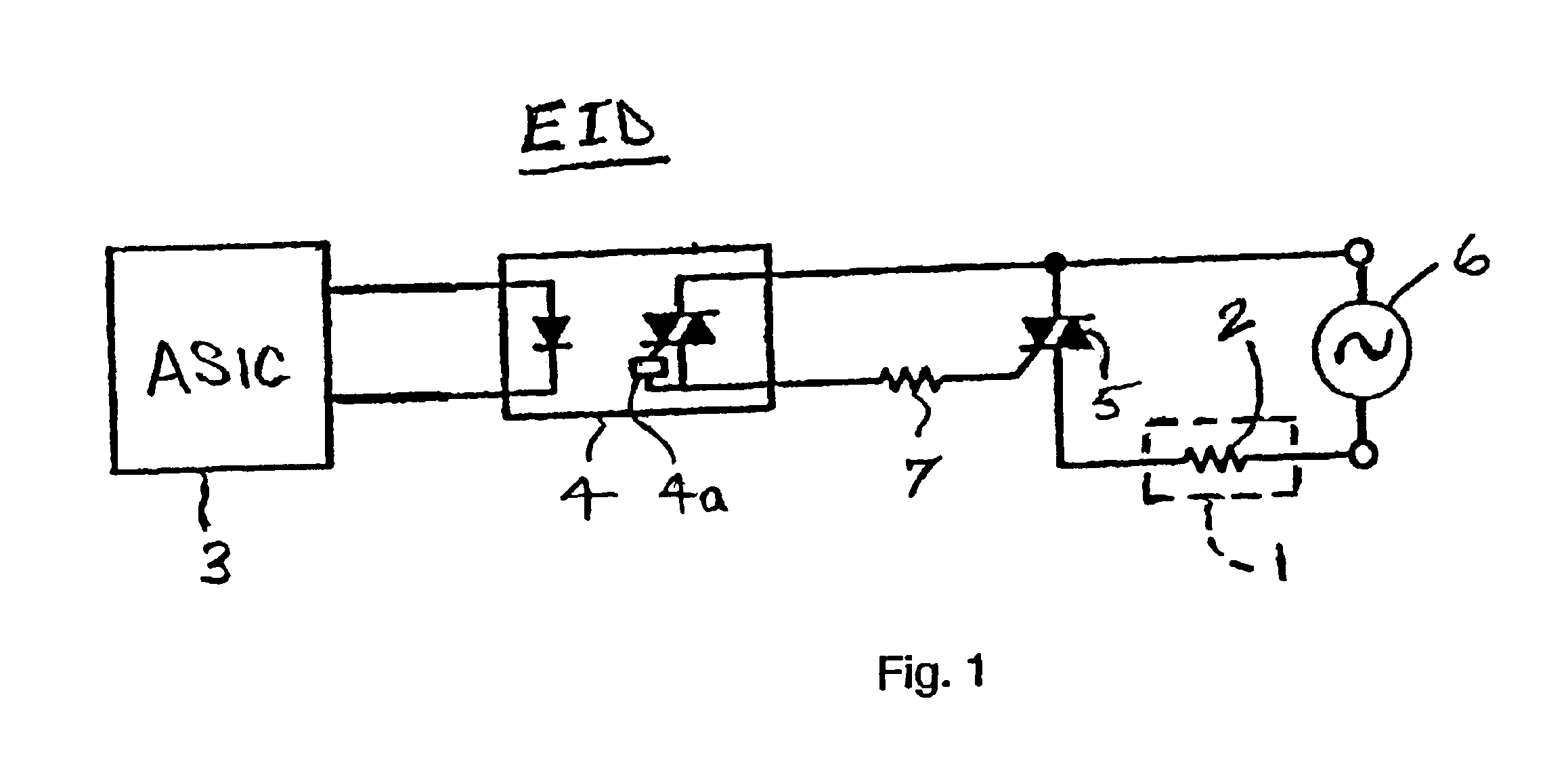
[0031]The present application provides a method of controlling a high power heater element in an electrical device. As a non-limiting example presented for illustration of the operating principals of the present application, the electrical device may comprise a fuser 1 such as is provided in an electrophotographic imaging device (EID), a portion of which is shown in FIG. 1, and the high power heater element 2 may comprise a tungsten lamp or equivalent heater having a power rating in the range of approximately 800 W-1000 W. The heater element 2 is controlled from a controller 3 of the EID, illustrated as an application specific integrated circuit (ASIC). Signals generated by the controller 3 in accordance with the method of the present application are passed to a zero-cross optoisolator triac driver circuit 4 including a zero crossing circuit 4a, such as an MOC3163 commercially available from Fairchild Semiconductor, which drives a power triac 5 to connect AC power from a source of A...


PUM


Abstract

A method for controlling power to an electrical load using dual pulse width modulation (PWM) to minimize in-rush current to the electrical load, such as a heater element. An output from a power source, supplying an alternating current, is modulated by a first PWM control signal to provide a first modulated power level to the electrical load. The first modulated power level is modulated by a second PWM control signal to control power supplied to the electrical load at the first modulated power level. The first PWM control signal operates to control the number of half cycles of current in order to provide one-third, two-thirds or full cycle power. The second PWM control signal operates to define a duty cycle and period for providing the power defined by the first PWM control signal to the electrical load.

Description

BACKGROUND OF THE INVENTION[0001]1. Field of the Invention[0002]The present invention relates to a method and apparatus for controlling power to an electrical load. More particularly, the present invention relates to a method and apparatus for controlling power to a high power heater element in a fuser of an imaging device to provide improved warm-up and temperature control characteristics.[0003]2. Description of Related Prior Art[0004]In printing, the amount of time it takes for the first page of a print job to be printed and to reach the printer's output bin is known as first copy time, and is an important feature to users of the printer. In conventional electrophotographic printers, the controlling factor for first copy time typically has been the amount of time it takes to warm up a cold fuser to a target temperature for performing a fusing operation.[0005]To optimize the first copy time, the fuser must be heated as fast as possible. In addition, it is necessary to maintain the ...

Claims


Application Information

Patent Timeline
Patent Type & Authority Patents(United States)
IPC IPC(8): G03G15/20
CPCG03G15/2039G03G2215/00586Y10S323/901
Inventor CAO, JICHANGGILMORE, JAMES D.MURPHY, CALVIN D.
Owner LEXMARK INT INC
Why Eureka
Try Eureka