Coated substrate

a technology of coating and substrate, applied in the field of coating substrate, can solve the problems of reducing affecting the service life of the insert, and affecting the service life of the insert, and achieve the effect of high corrosion environmen

Inactive Publication Date: 2005-08-16
KENNAMETAL INC
View PDF26 Cites 28 Cited by
  • Summary
  • Abstract
  • Description
  • Claims
  • Application Information

AI Technical Summary

Benefits of technology

[0013]Examples of applications of the method of the present invention include the manufacture and treatment of wear resistant cutting inserts, dies, punches, and other elements used in applications such as: metal stamping, punching, threading, blanking, milling, turning, drilling, boring, and other metal removal operations; mining and oil drilling, including fabricating or treating mining and drilling bits used in long wall and coal boring miners, tricone, percussive and rooftop drilling bits, road planing and other like applications; wood working applications, includi

Problems solved by technology

The carbide materials provide high strength but still may wear quickly when used in, for example, milling and other metal machining operations.
The utility of coated composite materials such as coated cemented carbides is limited by the strength of adhesion of the wear-resistant coating to the composite material.
Abse

Method used


Image

  • Coated substrate
  • Coated substrate
  • Coated substrate

Examples


example 1

[0049]A Bernex 250 CVD coating furnace was prepared by introducing into the coating chamber of the furnace a 10 l / min (liters / minute) flow of hydrogen gas to establish a 200 mbar hydrogen gas pressure within the chamber. The chamber was then heated to 850° C. A cemented carbide substrate composed of H-91 grade material available from Stellram, LaVergne, Tenn., was placed in the prepared furnace chamber and the chamber atmosphere was heated to 850°. H-91 grade material is composed of 88.5 weight percent tungsten carbide, 11.0 weight percent cobalt, and 0.5 weight percent of a mixture of TiC, TaC, and NbC. The material exhibits a hardness of 89.7 HRA, 14.40 g / cc density, and a transverse rupture strength of approximately 389,000 psi.

[0050]The flow of hydrogen gas was then stopped, and a concurrent flow of 20 l / min nitrogen gas and 1 l / min hydrogen chloride gas was introduced into the chamber to provide a chamber pressure of 800 mbar. Binder was etched to a depth of approximately 5 mic...

example 2

[0056]The Bernex 250 CVD furnace used in Example 1 was prepared using the procedure described in that example. A cermet substrate composed of SD-5 material, but having the same size and shape as the substrate in Example 1, was placed into the coating furnace and the furnace atmosphere was heated to 920° C. SD-5 material is a cermet grade material available from Stellram, LaVergne, Tenn., and is composed of TiCN and Mo2C particles in a Co / Ni binder. SD-5 material has the approximate elemental composition 45.2 Ti, 22.6 Mo, 10.9 C, 2.3 N, 19.0 Ni, and exhibits the following approximate mechanical properties: 91.8 HRA hardness, 6.30 g / cc density, and a transverse rupture strength of 300,000 psi. After heating the furnace atmosphere to 920° C., the Co / Ni binder was then etched to a depth of 5 microns from the substrate's surface using concurrent flows of hydrogen chloride and nitrogen gases at the flow rates, pressure, and reaction time used in Example 1 above. The furnace chamber was th...

example 3

[0057]Three Stellram cutting inserts of type SEKN-42-AF4B composed of SD-5 material (as described in Example 2) were first etched and then coated with the MT-milling coating by the following procedure.

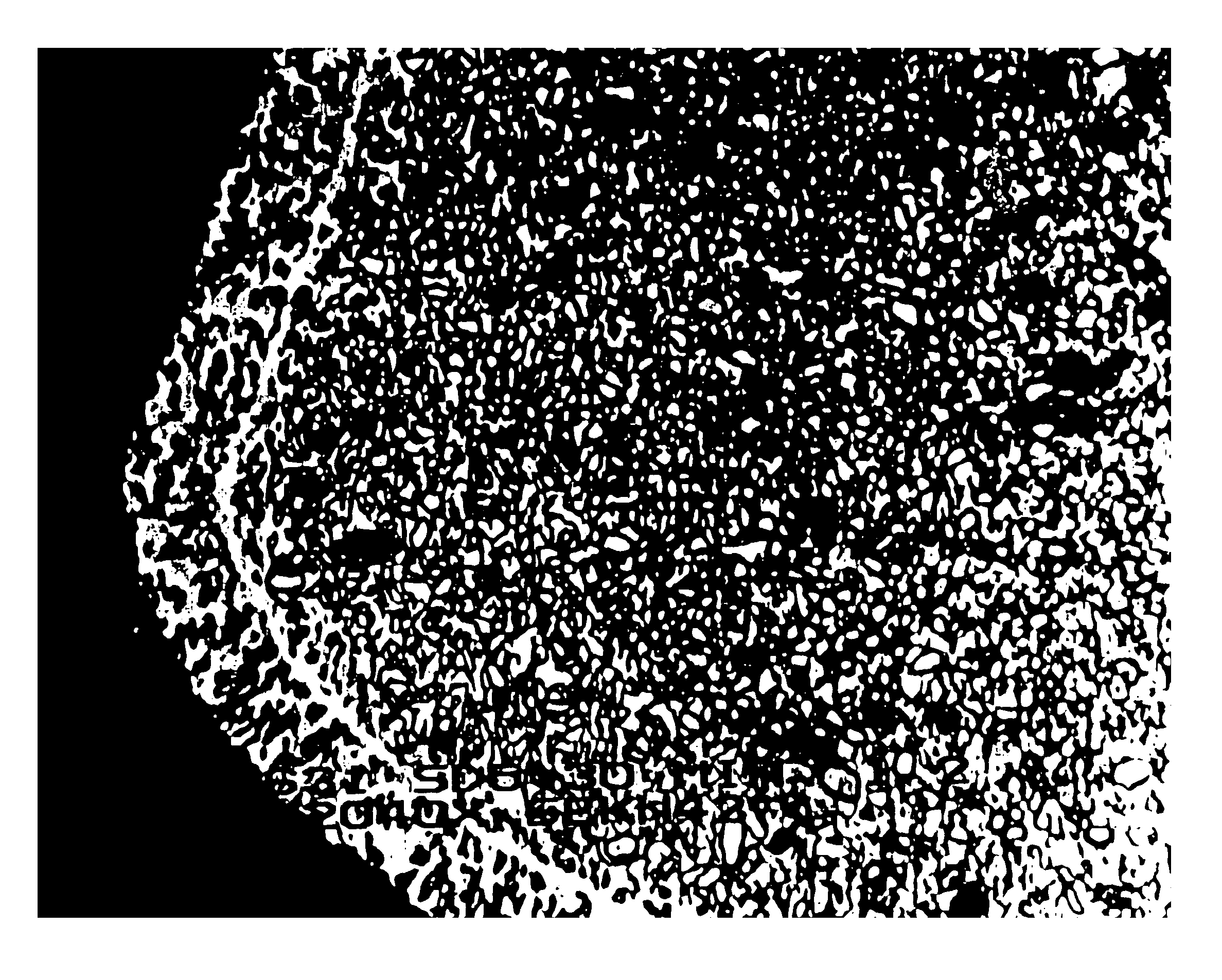
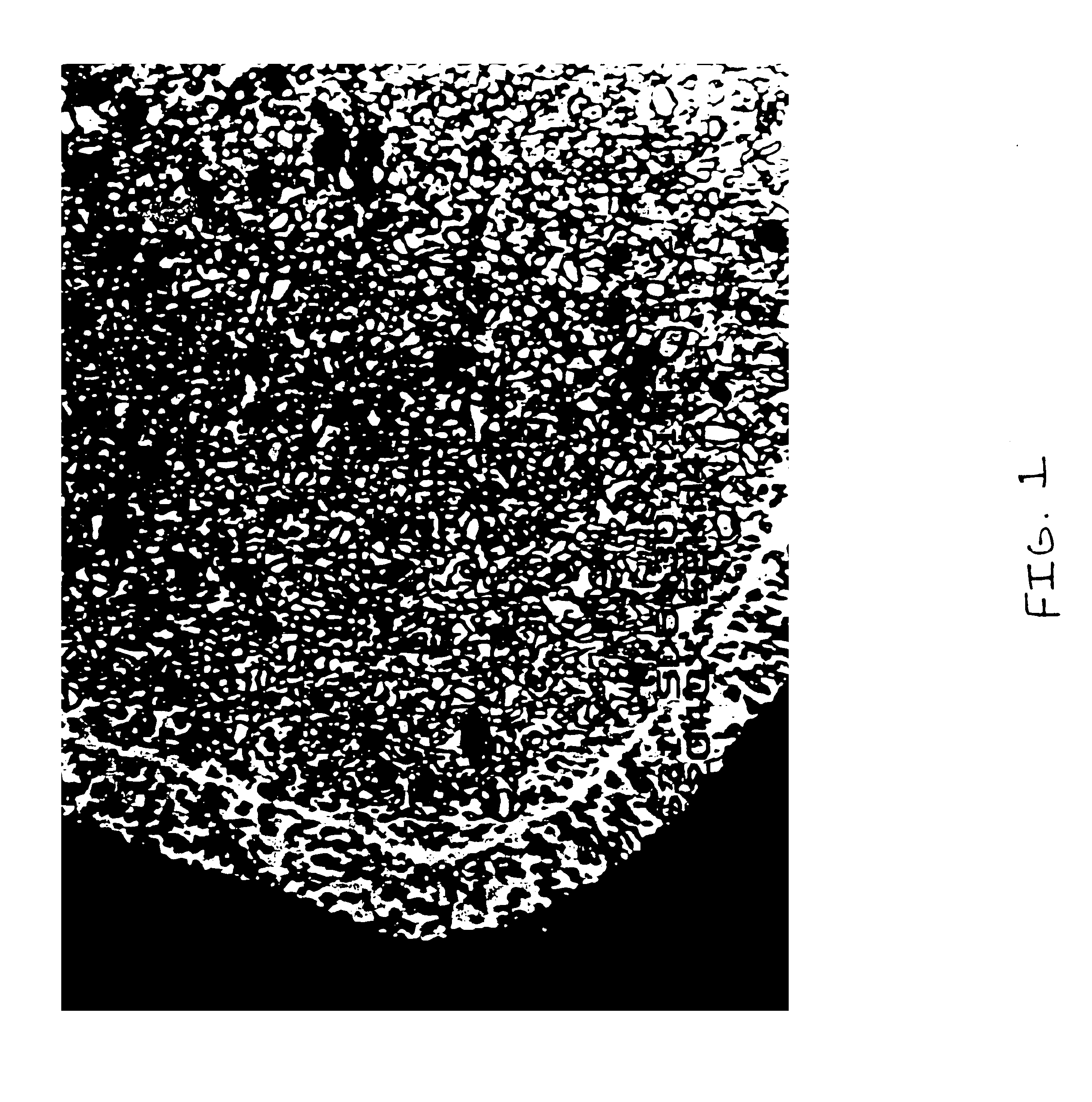
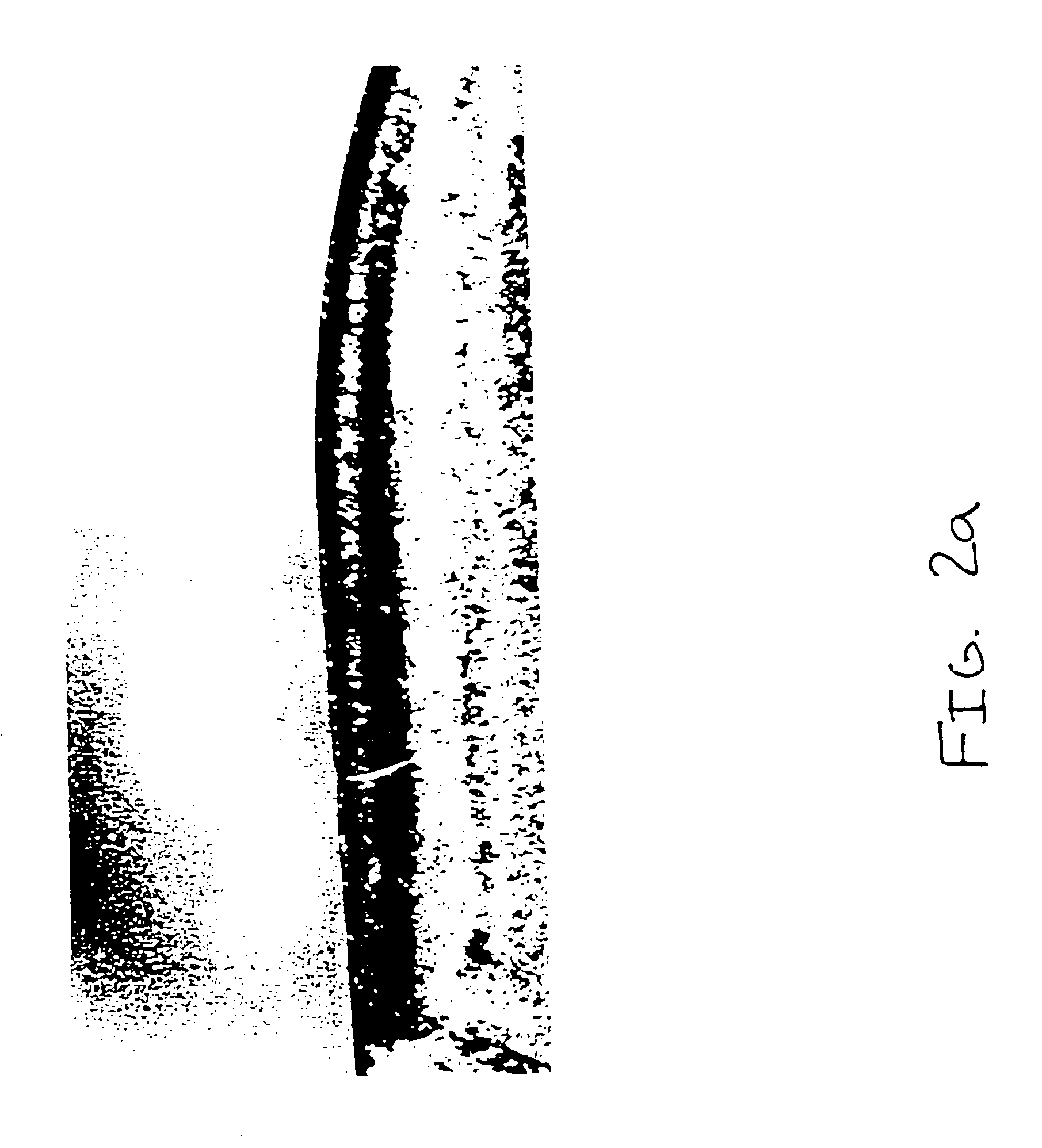
[0058]A CVD furnace chamber was prepared using the procedure described in Example 1. The SD-5 cutting inserts were then inserted into the furnace chamber and were etched using the procedure of Example 2. Once etched, the inserts were coated with MT-milling coating by the procedure of Example 1. The MT-milling coating produced on the etched inserts by the foregoing procedure was approximately 5 microns in thickness and the surface TiN layer infiltrated the voids etched in the inserts' surfaces. Approximately 5 microns of the coating extended above the inserts' surfaces. FIG. 1 is a photomicrograph (2040×) of a prepared cross-section through the surface of one of the etched and coated SD-5 inserts. The photomicrograph shows the infiltration of the MT-milling coating into the voids etched...


PUM

PropertyMeasurementUnit
Depthaaaaaaaaaa
Depthaaaaaaaaaa
Depthaaaaaaaaaa

Abstract

Method for removing a portion of the binder phase from the surface of a substrate that is composed of particles of at least a first phase joined together by the binder phase, and wherein the surface is etched by contacting it with a gas flow of an etchant gas and a second gas. The second gas is one or more gases that will not react with the substrate or the removed binder phase and will not alter the oxidation state of the substrate during etching.

Description

[0001]This is a divisional application of U.S. Ser. No. 09 / 095,398, filed Jun. 10, 1998, now U.S. Pat. No. 6,214,247.TECHNICAL FIELD AND INDUSTRIAL APPLICABILITY OF THE INVENTION[0002]The present invention relates to a method for etching composite material substrates and other substrates, and also is directed to a method for applying wear-resistant and other coatings to composite material substrates and other substrates. The present invention also relates to composite material substrates, which are comprised of particles of a hard constituent phase in a binder material phase that binds together the hard constituent particles, having wear-resistant and other coatings. The present invention finds application in any field in which it is advantageous to enhance the adhesion of a wear-resistant and other types of coatings to substrates. Examples of fields of application of the present invention include the manufacture and treatment of dies used in metal stamping, punching, threading, and...

Claims


Application Information

Patent Timeline
IPC IPC(8): C23C16/02C23C30/00C23C16/36C23C16/34
CPCC23C16/0236C23C16/34C23C30/005C23C16/36Y10T428/24975Y10T428/265
Inventor LEVERENZ, ROY V.BOST, JOHN
Owner KENNAMETAL INC
Why Eureka
Try Eureka