System and method for power saving memory refresh for dynamic random access memory devices after an extended interval

a dynamic random access memory and power saving technology, applied in static storage, information storage, digital storage, etc., can solve the problems of constant refresh of memory cells, capacitors can hold voltage, dram devices, etc., and achieve the effect of reducing the amount of power wasted and consuming less power

Inactive Publication Date:
View PDF18 Cites 20 Cited by
  • Summary
  • Abstract
  • Description
  • Claims
  • Application Information

AI Technical Summary

Benefits of technology

[0024]Through the addition of refresh signal delay means, an array comprised of less volatile DRAM devices, which only need to be refreshed after an extended interval, can be refreshed less frequently, consuming less power, while still using conventional DRAM refreshing control circuitry. The delay means delays externally generated refresh signals supplied to accommodate the refresh rate required by conventional DRAM memory devices but, in response, generates far less frequent delayed refresh signals. This reduces the frequency with which the less volatile DRAM devices will be refreshed, and powers off supporting addressing circuitry when it is not needed. Therefore, the delay means allows computing systems designed to use conventional DRAM devices to work with DRAM devices which only need to be refreshed after an extended interval and reduces the amount power wasted through unnecessarily frequent refresh cycles.

Problems solved by technology

However, DRAM devices have the disadvantage that their memory cells must be continually refreshed because of the inherently transitory nature of their storage technology.
First, a capacitor can hold a voltage only briefly.
In a DRAM memory device containing thousands of memory cells on a single piece of a semiconductor wafer, these capacitors are infinitesimal, and can only reliably maintain a voltage for microseconds.
Second, because these stored voltages dissipate so rapidly, reading the voltage after just a short interval requires a sense amplifier.
Constantly refreshing DRAM memory cells presents two problems.
First, refreshing memory cells slows the useful function of the memory.
Even though entire rows of an array are refreshed at a time, it still requires thousands of refresh operations to refresh every row in the array.
Moreover, these memory arrays cannot be accessed during a refresh cycle.
This waiting slows processing throughput.
Second, and even more problematic than processing delays, is the power consumed in the continual, rapid refreshing of these memory cells.
Resistance of the conductors through the memory array to address each and every transistor, in each and every row, in each and every column, consumes considerable power.
Regardless of which mode of refresh is employed, merely the number of devices needed to refresh the array suggests that significant power is consumed in refreshing the array.
The aggregate amount of power used to refresh the cells throughout an entire system memory becomes relatively immense.
The power expended in these refresh cycles is a significant problem.
Most significantly, excessive power consumption quickly exhausts battery power in increasingly popular portable computing devices.
The consumption of this power also generates a great deal of heat.
The problem remains that systems designed to work with conventional DRAM arrays are very common and standardized.
However, power still would be wasted because control systems designed to work with conventional DRAM cells would refresh the PCDRAM cells at a rate consistent with the refresh rate requirements of conventional DRAM cells.
The need to redesign circuitry interfacing with the DRAM devices to take advantage of the power savings possible with PCDRAM devices may, at least initially, limit the usefulness of and market demand for PCDRAM devices.

Method used


Image

  • System and method for power saving memory refresh for dynamic random access memory devices after an extended interval
  • System and method for power saving memory refresh for dynamic random access memory devices after an extended interval
  • System and method for power saving memory refresh for dynamic random access memory devices after an extended interval

Examples


first embodiment

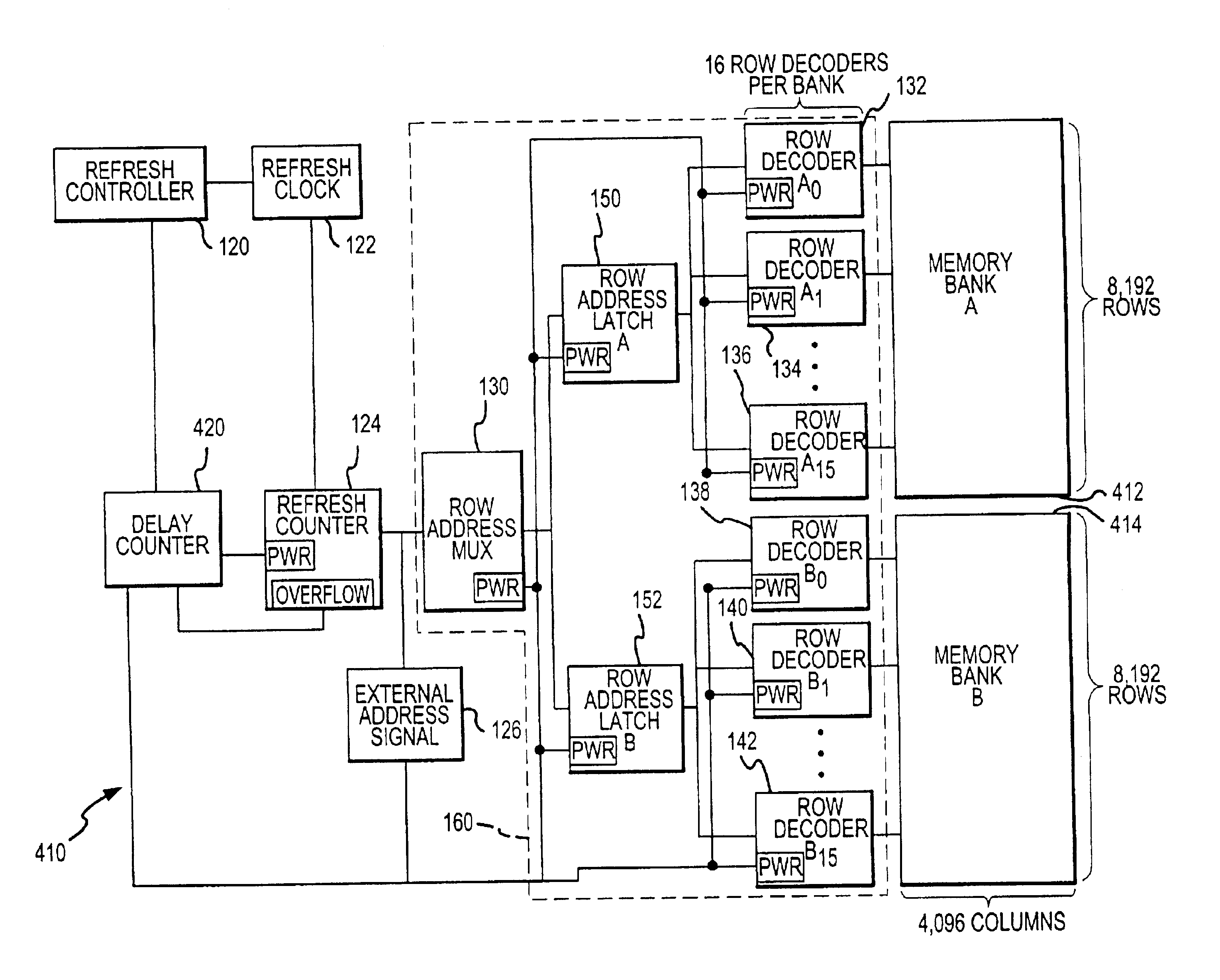
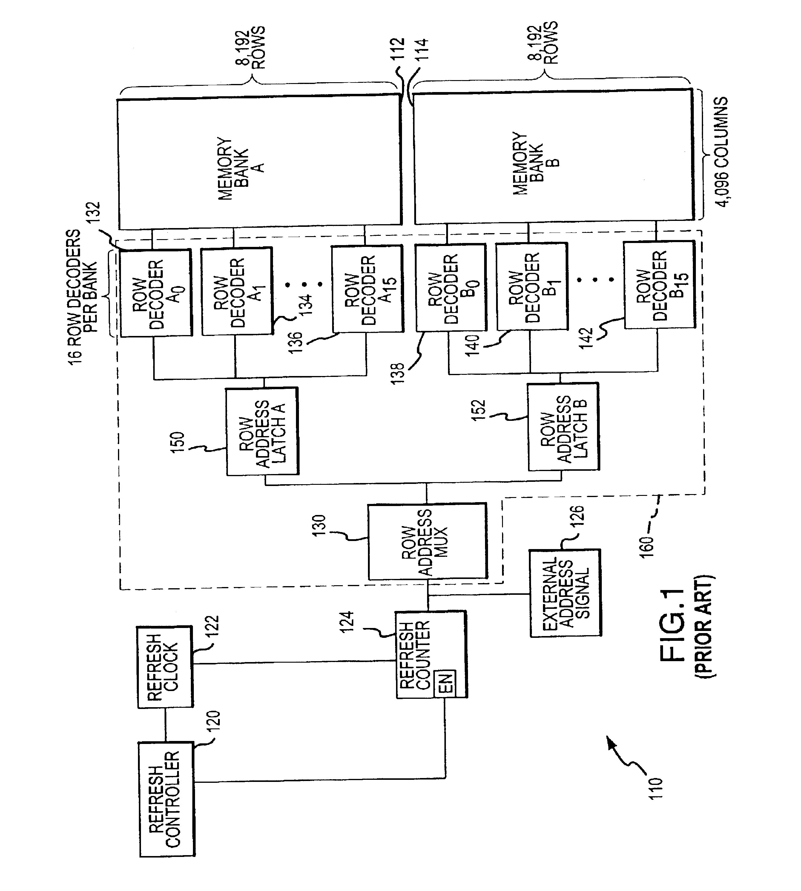
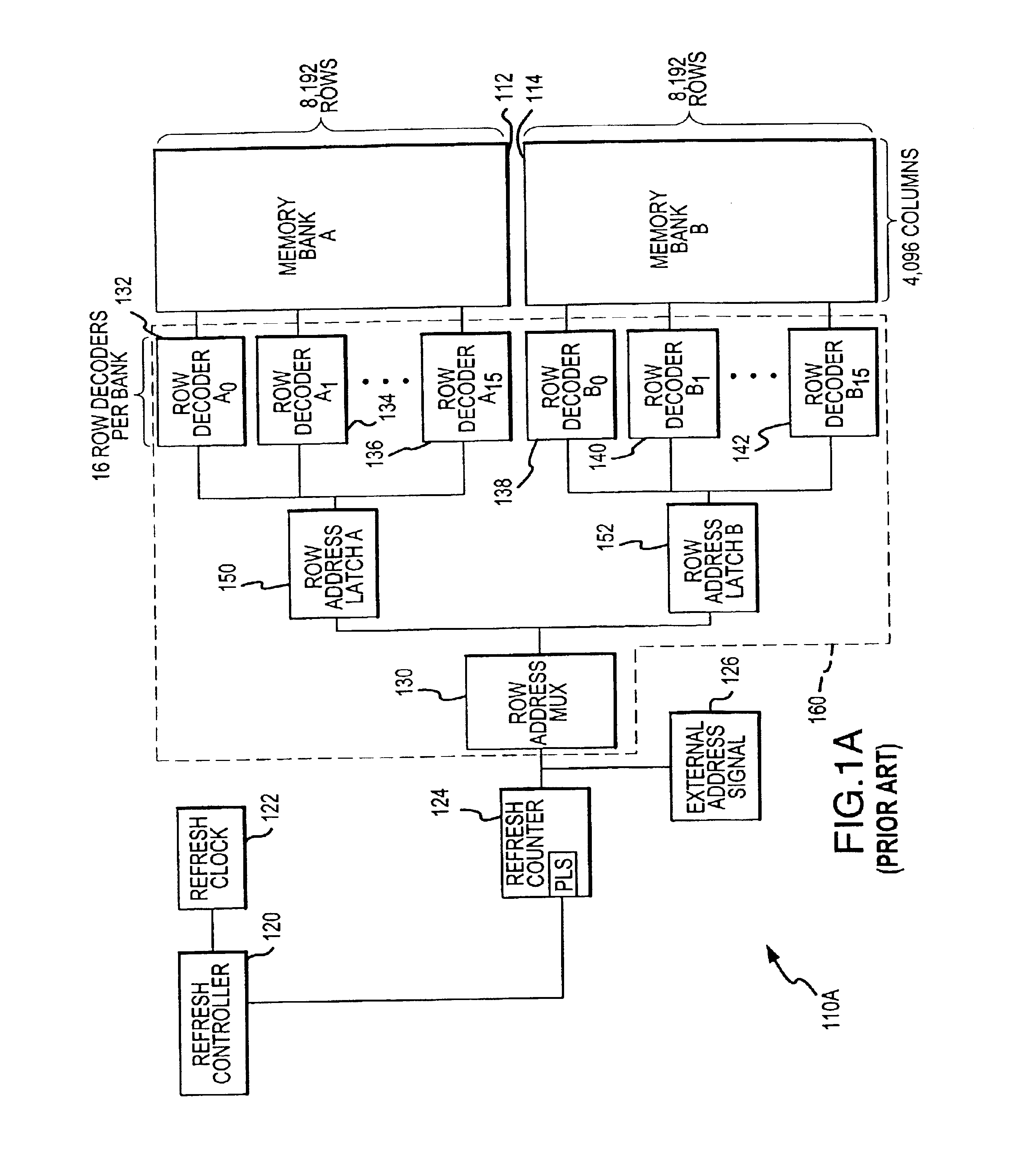
[0039]FIG. 4 depicts a memory array 410 very similar to the memory array 110 described in FIG. 1. Identical components shown in FIG. 4 have been provided with the same reference numeral, and explanation of their function and operation will not be repeated in the interest of brevity. The differences between the memory array 110 shown in FIG. 1 and the memory array 410 shown in FIG. 4 are twofold. First, the memory array 410 depicted in FIG. 4 has been adapted to use DRAM memory banks which only need to be refreshed after an extended interval 412 and 414. Second, to employ the invention and take advantage of the potential power savings afforded by the use of the DRAM memory banks which only need to be refreshed after an extended interval 412 and 414, a delay counter 420 has been added to the memory array 410. The memory array 410 shown in FIG. 4 employs burst refresh, as does memory array 110 in FIG. 1.

[0040]The delay counter 420 shown in FIG. 4 is a bit up counter which extends the i...

second embodiment

[0051]This second embodiment uses five additional control devices to control addressing of the memory array during refresh cycles, only three of which are powered on at one time when using a burst refresh mode. These additional devices allow for only six supporting devices to be activated at a time during a refresh cycle instead of thirty-five. This saves the wasteful powering and heat generation of twenty-nine superfluous devices. For a memory array eight bits in width, forty-eight devices would only need to be powered on at one time instead of two-hundred and eighty.

[0052]FIG. 6 depicts a memory array 610 very similar to the memory array 410 described in FIG. 4. PCDRAM memory banks which only need to be refreshed after an extended interval 412 and 414 still are being used, and to take advantage of their lower volatility, a delay counter 420 again is employed to extend the interval between refresh cycles. Five devices are added to the memory array 610 shown in FIG. 6: a bank segmen...


PUM


Abstract

A delay device is added to the addressing and refreshing circuitry of a DRAM array including DRAM devices less volatile than conventional DRAM devices and, thus, need not be refreshed as often. The delay device is connected to intercept refresh signals generated by a conventional DRAM refresh controller and initiates a refresh cycle after disregarding a predetermined number of refresh signals generated by the refresh controller whose total duration equals the interval by which the less volatile DRAM devices must be refreshed. The delay device also is adapted to power off circuitry needed to address the DRAM devices when the DRAM devices are not being refreshed or otherwise accessed. Additional circuitry is added to selectively power on only specific addressing devices actually needed to address those certain portions of the array being refreshed at that time.

Description

CROSS-REFERENCE TO RELATED APPLICATION[0001]This application is a continuation of pending U.S. patent application Ser. No. 10 / 002,707, filed Oct. 24, 2001, now U.S. Pat. No. 6,560,155 which is hereby incorporated by reference in its entirety.TECHNICAL FIELD[0002]The present invention is directed to dynamic random access memory (DRAM) devices, and, more particularly, to a system and method for saving power while refreshing DRAM devices such as programmable conductor DRAM (PCDRAM) devices which only need to be refreshed after an extended interval.BACKGROUND OF THE INVENTION[0003]Most computers and other digital systems have a system memory which often consists of dynamic random access memory (“DRAM”) devices. DRAM devices are fairly inexpensive because a DRAM memory cell needs relatively few components to store a data bit as compared with other types of memory cells. Thus, a large system memory can be implemented using DRAM devices for a relatively low cost. However, DRAM devices have...

Claims


Application Information

Patent Timeline
Patent Type & Authority Patents(United States)
IPC IPC(8): G11C11/406
CPCG11C11/406
Inventor HUSH, GLEN
Why Eureka
Try Eureka