Fiber optic security sensor and system with integrated secure data transmission and power cables

a technology of fiber optic sensors and security sensors, applied in power cables, photometry, burglar alarms by disturbance/breaking of stretched cords/wires, etc., can solve problems such as inapplicability of security sensor systems over large distributed networks

Inactive Publication Date: 2005-08-23
SENSTAR STELLAR CORP
View PDF23 Cites 22 Cited by
  • Summary
  • Abstract
  • Description
  • Claims
  • Application Information

AI Technical Summary

Benefits of technology

[0013]Previously in the prior art, the power conductor cables were located in the ground or mounted on structures either shared or separate from the sensor cables of the detection system while running in parallel with the sensor cables. The present invention is advantageous over the prior art in that the security sensor system can detect intruders cutting or tampering with the power conductor cables, as well as further detecting any other disturbance within proximity of the cabling. The present invention eliminates the necessity to monitor both the

Problems solved by technology

While additional fiber optic cables may distribute some level of power optically,

Method used


Image

  • Fiber optic security sensor and system with integrated secure data transmission and power cables
  • Fiber optic security sensor and system with integrated secure data transmission and power cables
  • Fiber optic security sensor and system with integrated secure data transmission and power cables

Examples


first embodiment

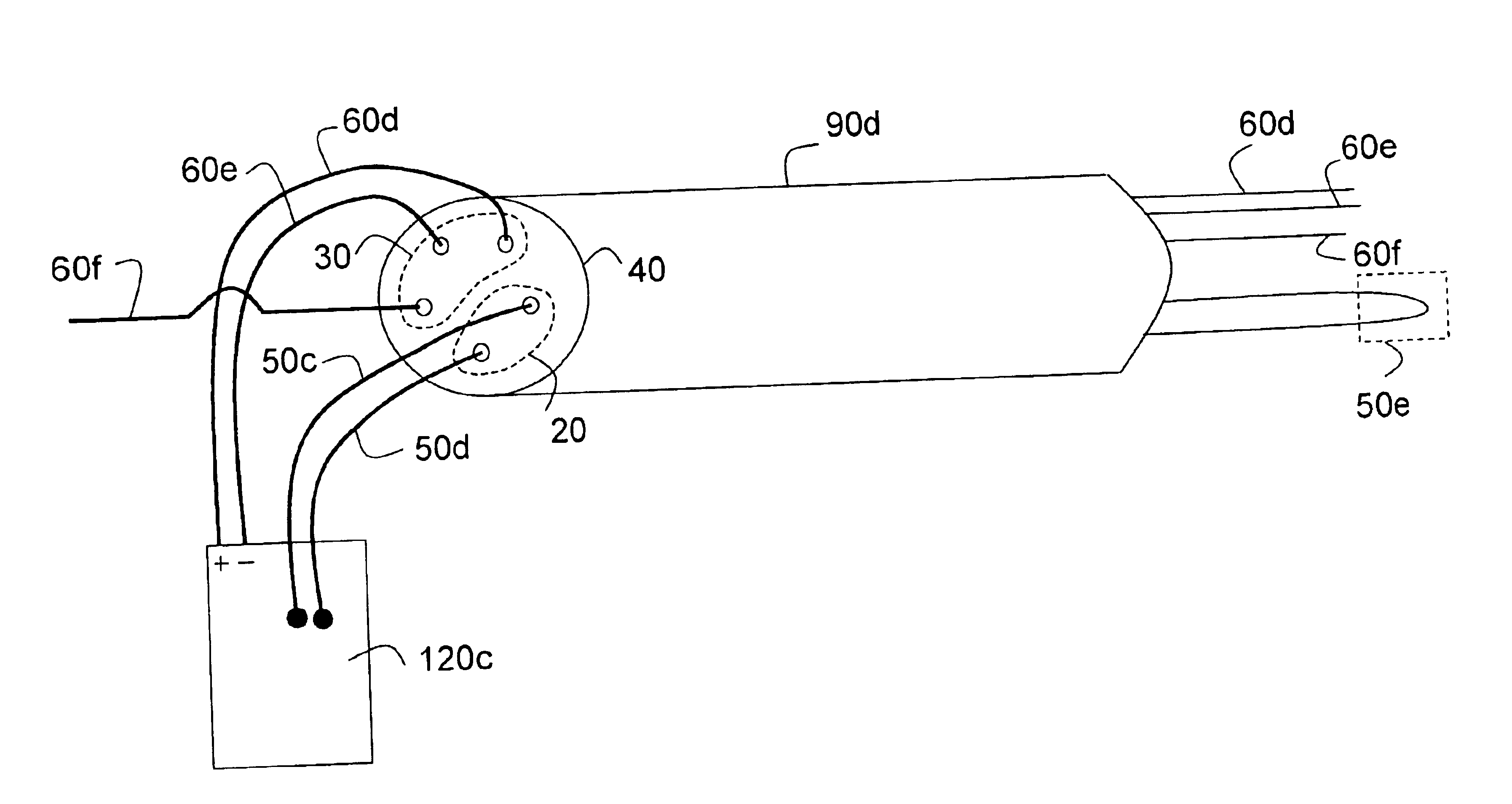
[0027]FIG. 3 is a block diagram of a security sensor system 85 having a security sensor cable equivalent to 10, of FIG. 2, according to the present invention. The security sensor system 85 includes a plurality of security sensor cables 90a, 90b, 90c and 90d, as detailed in FIG. 2, a main processing unit 110, and three secondary processing units 120a, 120b, 120c. The main processing unit 110 is in communication either directly or indirectly with the secondary processing units. While the main processing unit receives overall system security data, the secondary processing units may be required to perform certain functions in response to activities in their local sensing cables. Each of the secondary processing units 120a, 120b, 120c may process data signals received from security sensor cables 90a, 90b, 90c and 90d directly coupled to a given processing unit.

[0028]Two of the secondary processing units 120b and 120c are optionally coupled to video surveillance camera 125a and 125b, resp...

second embodiment

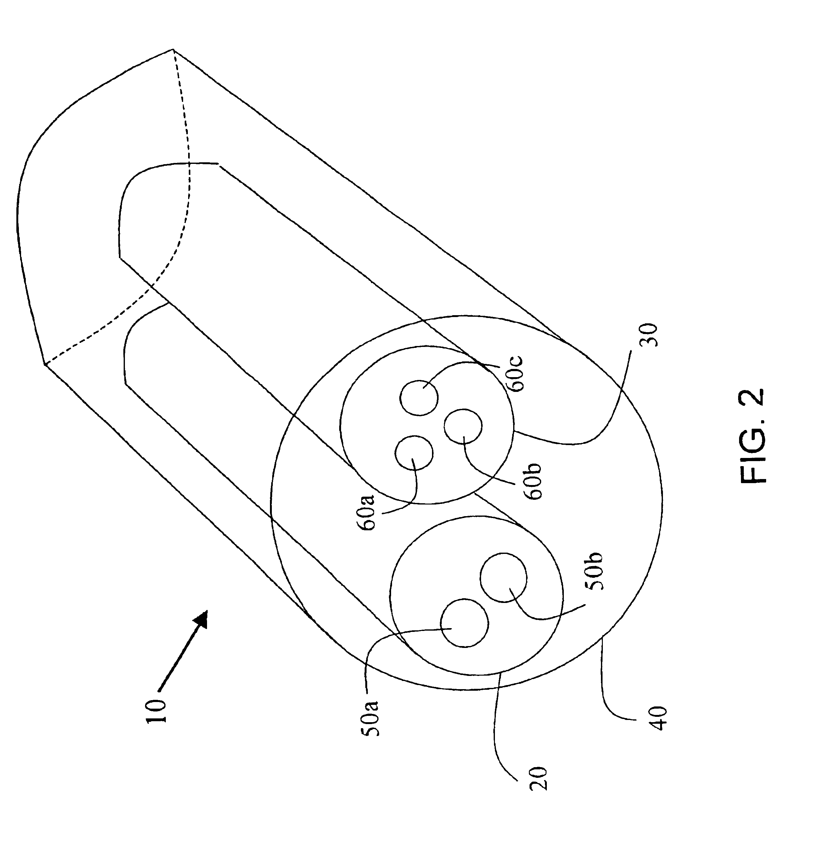
[0032]FIG. 5 is a block diagram of a security sensor system 85, of FIG. 3, within distributed data network 100 according to the present invention. The distributed data network 100 is an example of one implementation of the security sensor cable 10 of FIG. 2. In FIG. 5, the security sensor cable 10 is shown in the form of a plurality of security sensor cables 90a, 90b, 90c, 90d, 90e, 90f, and 90g, hereinafter termed security sensor data paths. Although the security sensor cables 90c, 90d, 90e, 90f, and 90g, are illustrated as separate security sensor cables they may be formed of a single security cable. To further clarify, the security sensor cables 90a, 90b, 90c, 90d, 90e, 90f, and 90g may be placed along the periphery of, or within, the various units 120a, 120b, 120c, 120d, 130a, and 130b. It is not necessary to break the security sensor cable at each unit 120a, 120b, 120c, 120d, 130a, and 130b in the data network 100. Only a few fiber optic cables, for data or sensing purposes, al...


PUM


Abstract

A fiber optic security sensor cable and system for using the cable. The cable includes a optical fiber encased in a first jacket, a power cable encased in a second jacket, and an overjacket encasing both the first jacket and the second jacket where the fiber is utilized to securely transmit data and provide a response to a sensed disturbance to the sensor cable. The system provides secure data transmission and power distribution via the sensor cable where one optical sensing fiber along the path of a data fiber responds to a sensed disturbance to the sensor cable. The system's sensor cable is enabled to detect disturbances at a processing unit where the sensor cable is either physically routed adjacent to the processing unit or within the processing unit. The system can further include more than one processing unit in the form of auxiliary units such as repeaters, power amplifiers, power outlets, data routers, and any similar electronic device. The system can also include a plurality of processing units which are arranged along the data path, wherein the sensor cable is physically routed within at least one of the processing units. The system's processing units may include at least one that is a microprocessor based signal processor.

Description

BACKGROUND TO THE INVENTION[0001]1. Field of Invention[0002]The present invention relates to a fiber optic sensor cable and a security sensor system. More particularly, the present invention relates to a security sensor cable having both optical sensing fiber, as well as power cables, within a secure cable jacket.[0003]2. Discussion of the Prior Art[0004]In the field of security sensor systems, outdoor sensors face challenges not found in indoor security situations. Environmental conditions, such as temperature extremes, rain, snow, animals, blowing debris, seismic effects, terrain and traffic, must all be taken into account. When functioning under these adverse conditions, the system must continue to maintain a high probability of detection while minimizing false alarms (alarms with unknown causes) and nuisance alarms (environment-related alarms), both of which may compromise and reduce the performance of the security system.[0005]Fence and wall-associated sensors are above-ground ...

Claims


Application Information

Patent Timeline
IPC IPC(8): G02B6/44G08B13/18G08B13/186G08B13/12G08B13/02H01B7/32H01B9/00H01B11/00H01B11/22
CPCG02B6/4469G08B13/124G08B13/186H01B7/328H01B9/005H01B11/22
Inventor RICH, BRIAN GERALDEVENSON, WILLIAM JOHN
Owner SENSTAR STELLAR CORP
Why Eureka
Try Eureka