Plastic wood fiber foam structure and method of producing same

a technology of wood fiber foam and composite foam, which is applied in the field of continuous production of plastic/wood fiber composite foam, can solve the problems of insufficient moisture content definition in the conventional moisture content formula, the foam structure is very uniform, and the potential industrial application of wood fibers is limited. to achieve the effect of preventing any damage to wood fibers

Inactive Publication Date: 2005-08-30
PARK CHUL +2
View PDF14 Cites 21 Cited by
  • Summary
  • Abstract
  • Description
  • Claims
  • Application Information

AI Technical Summary

Benefits of technology

[0017]The present invention encompasses the use of both, chemical blowing agents (CBA) and physical blowing agents (PBA), for producing fine-celled plastic / wood-fiber composite foams. Uniformly distributed fine cells enhance material properties such as tensile strength, toughness, impact strength, insulation and surface quality, in addition to reduction in cost.
[0018]The present invention utilizes a CBA or a PBA to generate gaseous material, which is dispersed or dissolved in the polymer matrix under high temperature and pressure. The dispersed gases become nuclei for the bubbles when the pressure is rapidly reduced at the die exit, whereas, the dissolved gases produce a large number of nuclei when subjected to a rapid pressure drop and / or sheer stress, leading to Spinodal decomposition of the dissolved gases from the polymer matrix [19], But these effects result in the creation of large number of bubbles which leads to the production a very fine cell structure in plastic / wood-fiber composite foams. The cell size and uniformity of distribution achieved with this invention, for producing wood-fiber / plastic composite foams, is far superior to what has been obtained in the prior arts.
[0020]As mentioned earlier, moisture and other volatile gases are released from the wood-fiber, even after it has been dried and / or devolatilized, whenever its temperature is elevated beyond or around the drying temperature. The solubility of H2O is very low in polymer and so, if it is present, it may remain un-dissolved in the melt and deteriorate the cell morphology. Also, the volatile gases may cause formation of big voids in the final products if the processing pressure is not high enough compared to the solubility pressures of the volatile gases. Accordingly, by determining the critical drying and processing temperature, the H2O and volatile emissions are minimized as much as possible to achieve this goal becomes crucial.
[0022]Although preference is given to a drying temperature lower than 170° C. in order to prevent any damage to wood-fibers from thermal degradation, a short time exposure of wood-fibers to a temperature higher than 170° C., for drying or devolatilization, has proved to produce a fine-celled foam structure, without significant degradation of mechanical properties or any undesirable composite structures. Acceptable results have been obtained with the wood-fiber drying or devolatilizing temperature as high as 185° C. This holds true for all the processes (A to F) described in a later section.

Problems solved by technology

Although plastic / wood-fiber composites have been commercialized, and can compete with certain plastic and wood products, their potential industrial applications have been limited because of their low impact strength and high density compared to natural wood and certain plastics [4].
This results in the foam structure being very non-uniform.
Therefore it is not sufficient to define the moisture content in terms of the conventional moisture content formula used for lumber wood.
However, the major draw back with it is that it is batch processing and would involve additional costs associated with such processes.
The final product produced using this process is, however, heavier than the wood it replaces.
However, it is difficult to control the expansion process and the foam structure obtained is non-uniform.
One of the fundamental problems is that the moisture and volatiles from even the dried wood-fibers are typically gradually released, as long as it is being heated.

Method used


Image

  • Plastic wood fiber foam structure and method of producing same
  • Plastic wood fiber foam structure and method of producing same
  • Plastic wood fiber foam structure and method of producing same

Examples


example for process b

Material

[0074]HDPE Grade 2710 from Nova was used as the base polymer for the composites. 50 wt % standard wood-fibers softwood grade 12020, supplied by American Wood Fibers, were used. 3 wt % coupling agent (Fusabond adhesive resin E-MB-100D from Dupont, Canada) was used for improving the adhesion between the PE and the wood-fiber. Commercial CO2, upto 4 wt %, from Matheson Gas was used as the PBA. All the materials were used as received.

Experimental Setup and Procedure

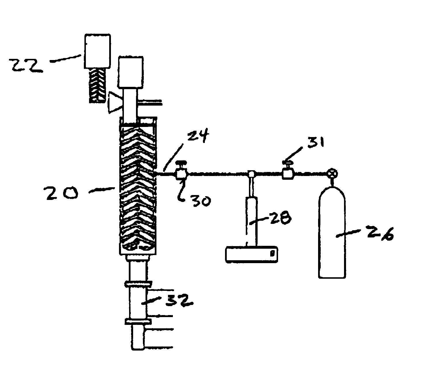
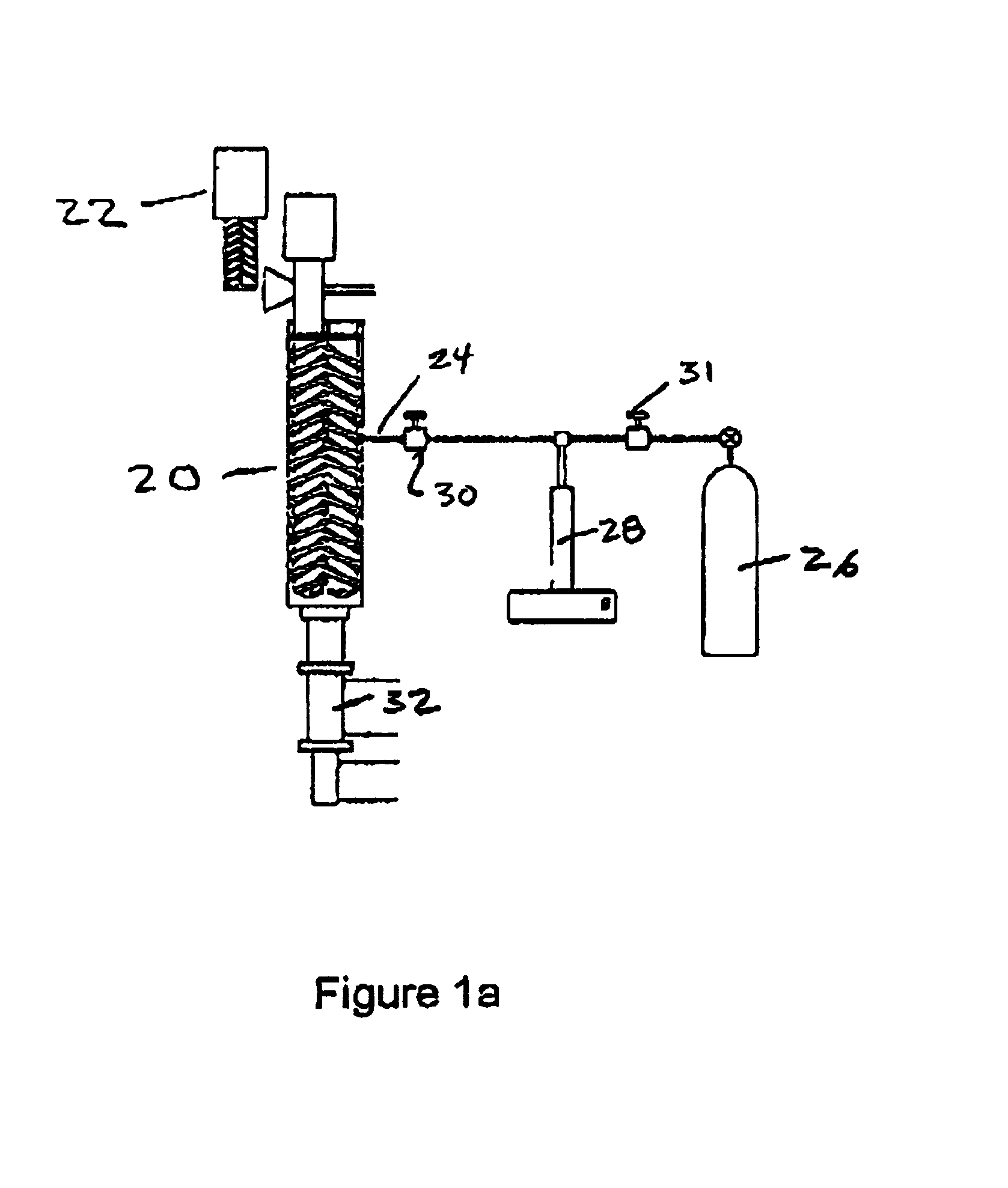
[0075]A schematic of the equipment for process B is shown in FIG. 2a. In the preparatory stage, un-dried wood-fiber is mixed with the polymer powder / pellets, a coupling agent, and a nucleating agent such as talc in a dry blending tumbler, and fed into the first twin-screw extruder 40, using a feeder 22. The temperature at the exit of this extruder was maintained at the highest processing temperature, which in this case was 180° C., for completely vaporizing the moisture and other volatiles from the wood-fiber. The out...

example for process d

Material

[0088]HDPE Grade 58G from Novacor was used as the base polymers for the composites. The wood-fibers were standard softwood (pine) grade 12020, supplied by American Wood Fibers. The CBA, Hydrocerol Compound (HC), was supplied by Boehringer Ingelheim. The coupling agent used for improving the adhesion between the PE and the wood-fiber was Fusabond adhesive resin E-MB-100D from Dupont, Canada. All the materials were used as received.

Experimental Setup and Procedure

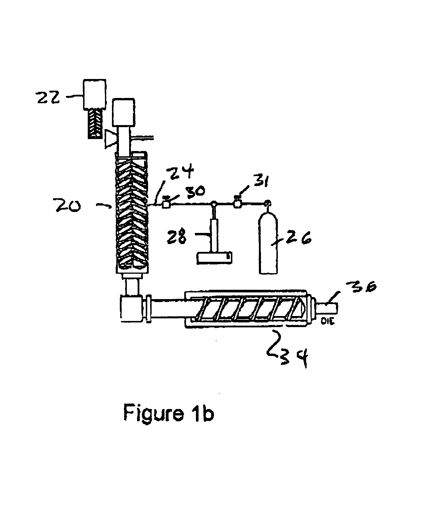
[0089]The cascade or tandem extrusion system shown in FIG. 4a was used in the experiments. The mixtures were dry blended and fed into the first twin-screw extruder 40, using a feeder 22. The temperature in this extruder was maintained at a level sufficient for vaporizing the moisture (145° C. to 170° C.), but not so high as to cause the decomposition of CBA and the degradation of wood-fiber. The output of this extruder was fed into the second extruder 42. At the interconnection, which was open to atmosphere, substanti...


PUM

PropertyMeasurementUnit
temperatureaaaaaaaaaa
processing temperatureaaaaaaaaaa

Abstract

A process for producing plastic / wood fiber composite foamed structures includes the steps of pre-drying wood fiber filler; mixing it with plastic to form a mixture; feeding the mixture into an extruder; introducing and mixing a blowing agent; subject the mixture to high shear forces and extruding the mixture to produce a plastic / wood fiber composite foamed structure. The filler has a degradation temperature and an active volatization temperature. During the pre-drying step the temperature is maintained below the degradation temperature. During the mixing step the mixing temperature is maintained below the active volatilizing temperature. During the introducing and mixing step a blowing agent is introduced into the plastic / wood fiber mixture and is mixed therewith to produce a plastic / wood fiber / gas mixture. During the subjecting step the plastic / wood fiber / gas mixture is subjected to high shear forces in the presence of high pressures and the temperature is maintained below an active volatilizing temperature.

Description

CROSS REFERENCE TO RELATED PATENT APPLICATION[0001]This patent application relates to U.S. Provisional Patent Application Ser. No. 60 / 288,445 filed on May 4, 2001 entitled PLASTIC WOOD FIBER FOAM STRUCTURE AND METHOD OF PRODUCING SAME which is incorporated herein by reference.FIELD OF INVENTION[0002]This invention relates to the continuous production of plastic / wood fiber composite foams, in an extrusion process, and is more particularly directed to increasing the number of cells and reduction of cell size and thereby, improving the distribution of cells in the plastic matrix.BACKGROUND OF THE INVENTION[0003]The end of twentieth century is characterized by a large increase of thermoplastic consumption with the consequent increase in their prices [1,2]. This situation has created an impetus for cost reduction by utilizing fillers in thermoplastic to form composite materials [3]. Composite materials also offer the opportunity to utilize the favorable properties of the constituent comp...

Claims


Application Information

Patent Timeline
Patent Type & Authority Patents(United States)
IPC IPC(8): B29C47/00B29C47/50B29C47/10B29C47/38B27N3/00B27N3/28B27N1/00B27N3/08C08J9/00B29C44/02B29C44/12B29C48/05B29C48/38B29C48/385B29C48/39B29C48/40B29C48/41
CPCB27N1/00B27N3/005B27N3/28B29C47/0004B29C47/0014B29C47/50C08J9/0085B29C47/366B29C47/369B29C44/12B29C47/1045B29K2105/06C08J2201/03B29C47/1018B29K2105/16B29C48/05B29C48/022B29C48/287B29C48/2886B29C48/385B29C48/39B29C48/38B29C48/41B29C48/40
Inventor PARK, CHUL B.RIZVI, GHAUS M.ZHANG, HAIOU
Owner PARK CHUL
Why Eureka
Try Eureka