

Electrostatic energy generators and uses of same
- Summary
- Abstract
- Description
- Claims
- Application Information
AI Technical Summary
Benefits of technology
Problems solved by technology
Method used
Image

Examples
Embodiment Construction
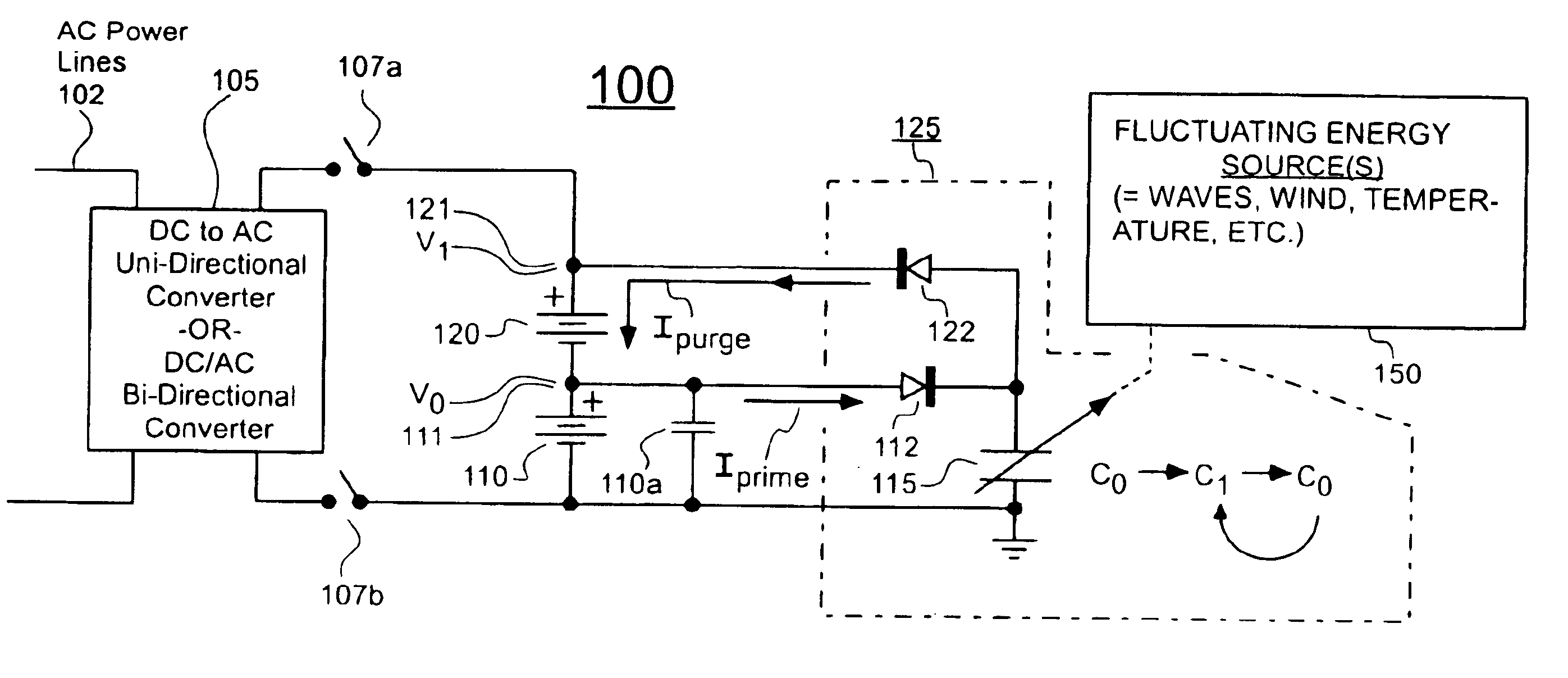
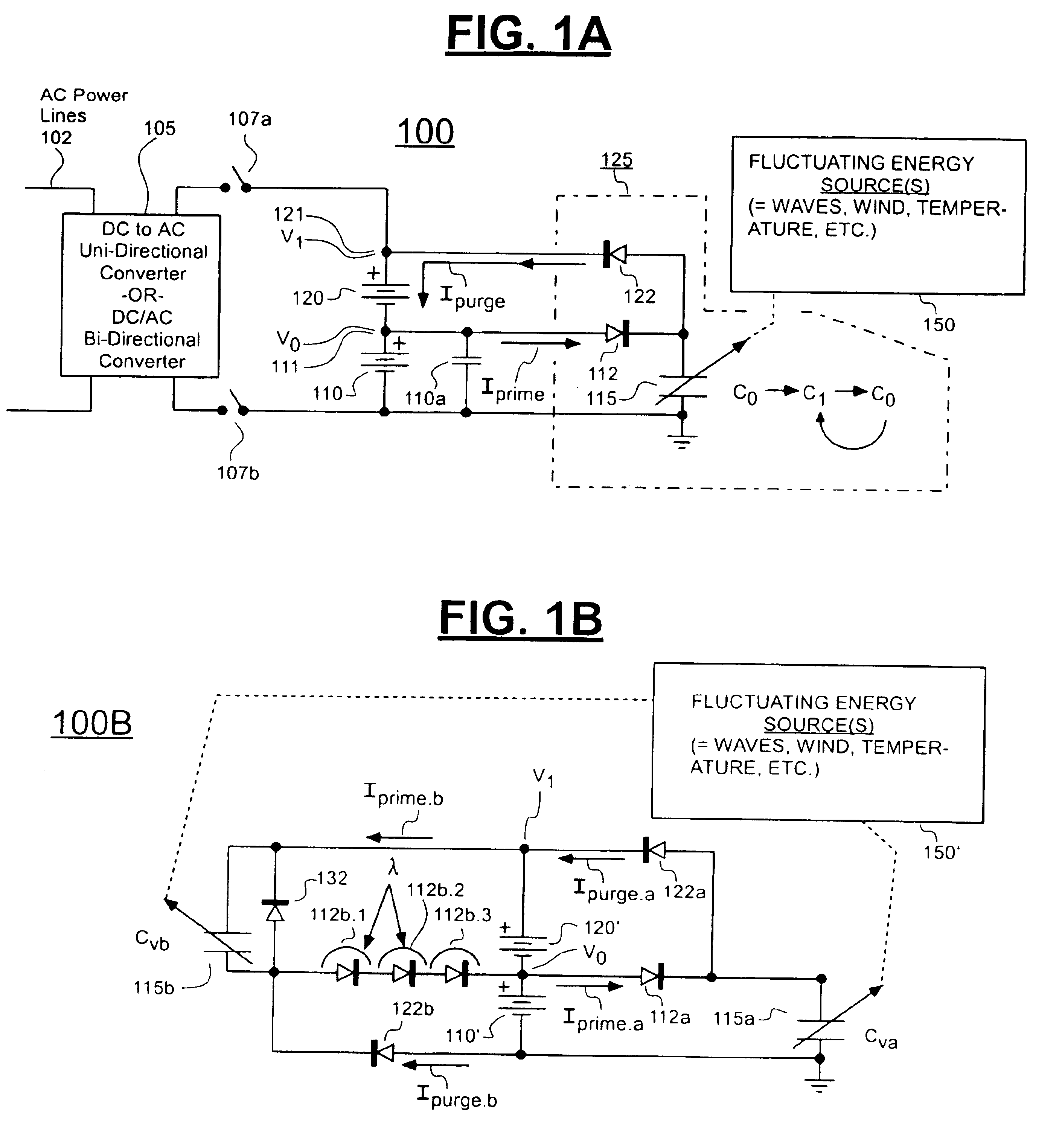
[0065]The idea of separating the plates of a capacitor while charge is trapped on its plates is notoriously old and may be found in elementary physics books. It is also well known that the relationship between attractively-stored charge (Q), voltage (V), and electric capacitance (C) may be expressed as, Q=VC and that the electrostatic energy in a charged capacitor may be expressed by: w=½*C*V2. Numerous electrostatic generating machines have been built wherein charge is trapped on some form of conveyor (e.g., a conveyor belt or wheel) and moved away from its point of trapping so as to thereby increase the potential energy level of the trapped charge by astronomical proportions. Voltages can climb to the point where an electric arc discharges across air for the purpose of providing entertainment. These various kinds exploitations of the effect can be characterized as being hampered by greed and lack of patience. It is all too tempting to want to get a big output for essentially nothi...
PUM
 Abstract
Description
Claims
Application Information