
Stable and high speed full range laser wavelength tuning with reduced group delay and temperature variation compensation

Inactive Publication Date: 2005-08-30
LIN JIAN
View PDF11 Cites 9 Cited by
  • Summary
  • Abstract
  • Description
  • Claims
  • Application Information

AI Technical Summary

Benefits of technology

[0007]It is therefore an object of the present invention to provide a tunable laser implemented as a fiber-based ring cavity that can achieve full range high speed tuning operated with wavelength stability with reduced group delay and temperature-dependent fluctuations such that the above mentioned limitations and difficulties can be resolved.
[0008]Specifically, it is an object of the present invention to provide a tunable laser implemented as a fiber-based ring cavity operated with tunable filter combined with a periodic filter with central wavelengths anchored to the ITU grids to achieve full range high speed wavelength tunings.
[0009]Another object of the present invention is to provide a tunable laser implemented as a fiber-based ring cavity implemented with dispersion compensation fibers (DCF) of different lengths to reduced the difference between group delays when tuning the laser wavelengths such that high speed tuning may further enhanced.
[0010]Another object of the present invention is to provide a new type of fiber connection configurations by arranging the longitudinal axes of two fibers with a predefined angular difference such that the temperature induced phase changes can be minimized and wavelength stability of a tunable laser implemented with a fiber-based ring cavity can be further improved.
[0012]In a preferred embodiment, this invention further discloses a fiber-based ring cavity tunable laser that includes an optical tunable fiber (OTF) for tuning a central wavelength of the tunable laser. This tunable laser further includes a fiber-based ring comprising a dispersion compensation fiber (DCF) having a first segment connected to a first end of the OTF and a second segment connected to a second end of the OTF opposite the first end of the OTF. The first segment and second segments having different lengths for reducing a group delay difference of an optical transmission.

Problems solved by technology

Conventional technologies of optical fiber communication networks are still confronted with several technical challenges and difficulties to achieve high speed full range wavelength tuning while maintaining wavelength and phase stability as the optical transmissions encounter wavelength dispersions over long distance transmission and operated over greater ranges of temperature fluctuations.
However, conventional techniques for such wavelength tunings are still limited by a lower achievable tuning speed not compatible with the requirements of the next generation fiber telecommunication applications.
To achieve a full range wavelength tuning in C and / or L band, the laser suppliers in optical fiber telecommunication are confronted with another technical difficulty of maintaining laser stability while tuning the wavelength.
As the group delay varies with the wavelength in the fiber laser, tuning of wavelength will cause a change of the equivalent cavity length and that in turn causes the instability of the fiber laser.
However, as the group-delay difference between two tuning wavelengths is increased, the corresponding fiber length adjustment has to increase also and that leads to a reduced tuning speed.
Even though a delay line can be used instead, but the tuning speed is usually limited with the driving motor and not practical for a mode locked fiber laser.
As the temperature changes, the light path variations induced by temperature variations within the fiber cavity will again cause the instability of the laser operation and degrade the laser performance.

Method used


Image

  • Stable and high speed full range laser wavelength tuning with reduced group delay and temperature variation compensation
  • Stable and high speed full range laser wavelength tuning with reduced group delay and temperature variation compensation
  • Stable and high speed full range laser wavelength tuning with reduced group delay and temperature variation compensation

Examples


Embodiment Construction

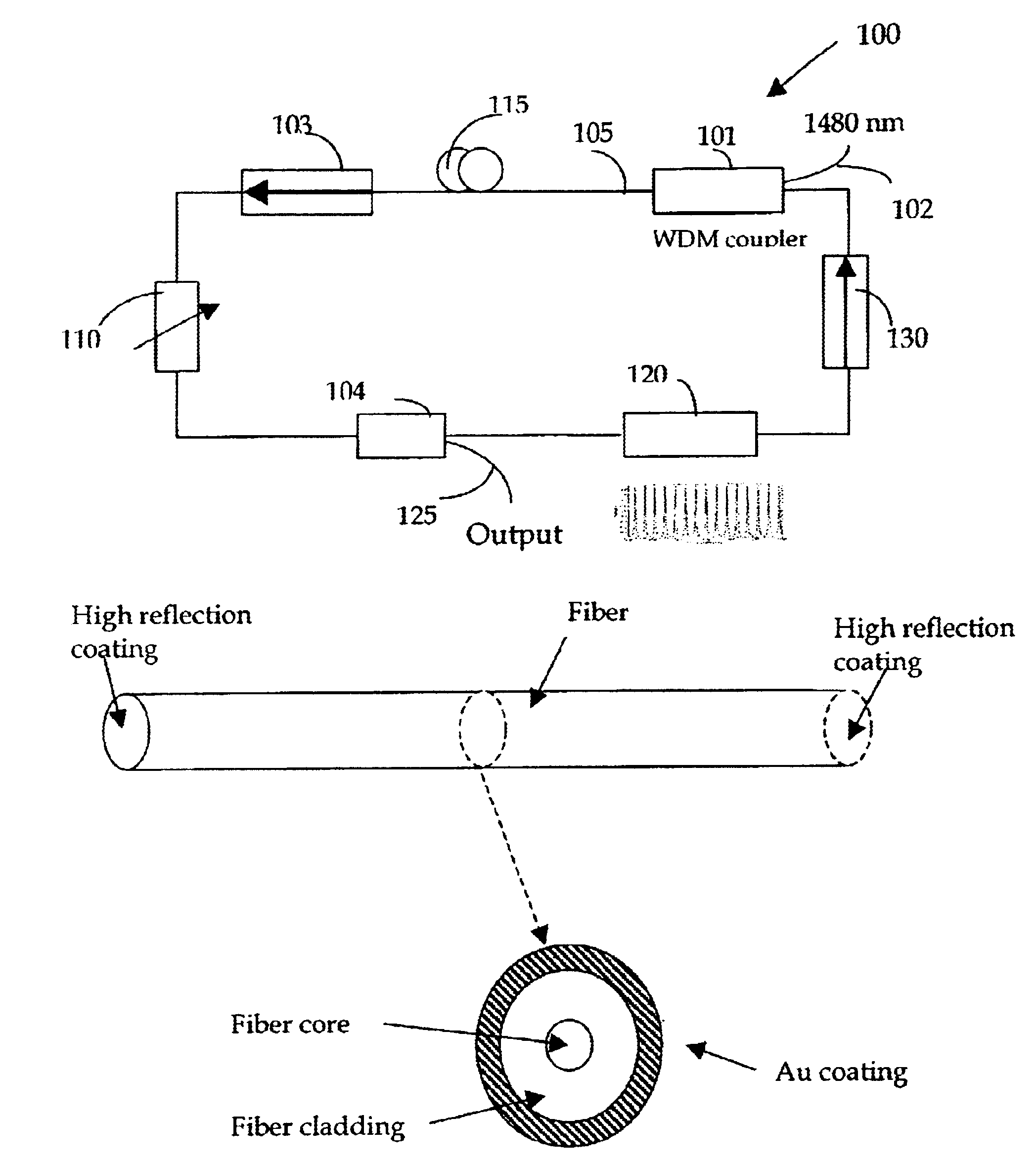
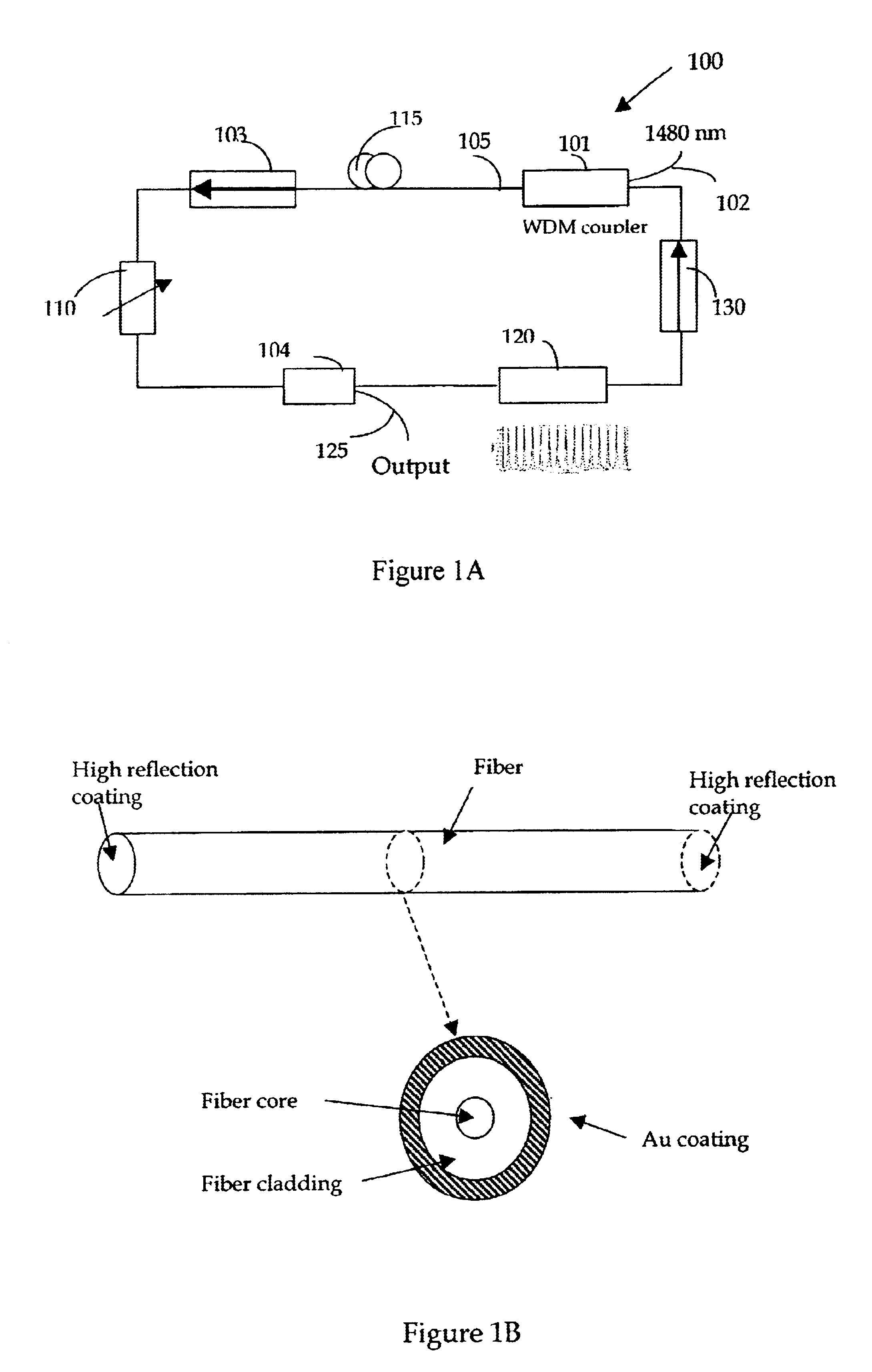
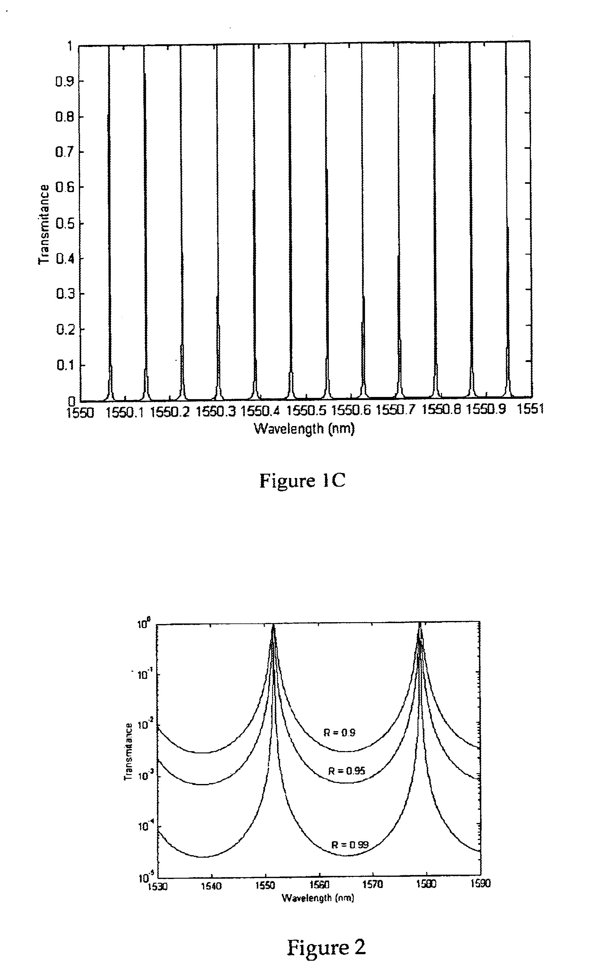
[0028]Referring to FIG. 1A for a specialty fiber based ring cavity 100. The fiber based ring cavity 100 includes an electro-optical tunable filter 110 to achieve a high speed wavelength laser tuning. A specialty fiber 105 is used in the cavity to provide a way of confining the light while maintaining the polarization. A polarization maintaining Erbium-doped fiber (PMEDF) 115 is used in the cavity as a gain medium and to avoid lasing instability due to polarization change in the laser cavity. The fiber based ring cavity 100 further includes a periodic filter 120 to generate a spectral comb response. This comb FP filter 120 has a high finesse with a bandwidth close to the narrow line width of the fiber laser and a free spectral range of 100 GHz or 50 GHz. The center wavelengths of the filter are anchored with the International Telecommunication Union (ITU) grids such that the lasing wavelength is matched with the telecommunications standards. The electronically tunable filter 110 is a...


PUM


Abstract

A fiber-based ring cavity tunable laser is disclosed in this invention that has full range high speed tuning achieved by combining a optical tunable filter with a period comb-shaped filter with central wavelengths anchored on International Telecommunication Union (ITU) grids. By using segments of dispersion managed fibers with predefined segment lengths the group delay differences are also reduced. The temperature sensitivity of optical transmission is also reduced by arranging the longitudinal axis of different segments of the optical fibers to orient with a relative angular difference, e.g., with an angular difference of ninety degrees.

Description

[0001]This Formal Application claims a Priority Date of Jan. 5, 2002 benefited from three Provisional Application Nos. 60 / 346,269, 60 / 346,270, and 60 / 346,271, filed by the same Applicant of this Application on Jan. 5, 2002.FIELD OF THE INVENTION[0002]The present invention relates generally to apparatuses and method for providing tunable laser source for optical fiber signal communication systems. More particularly, this invention relates to new configurations and methods for providing stable tunable laser source that is tunable at higher speed, having broader tuning ranges with reduced group delays and less fluctuations resulting from temperature variations.BACKGROUND OF THE INVENTION[0003]Conventional technologies of optical fiber communication networks are still confronted with several technical challenges and difficulties to achieve high speed full range wavelength tuning while maintaining wavelength and phase stability as the optical transmissions encounter wavelength dispersion...

Claims


Application Information

Patent Timeline
IPC IPC(8): H01S3/106H01S3/06H01S3/067
CPCH01S3/06791H01S3/106
Inventor LIN, JIAN
Owner LIN JIAN
Learn More