
Flow meter

a flow meter and flow rate technology, applied in the direction of machines/engines, electrical control, instruments, etc., can solve the problems of no processing means for computing volumetric flow rate, no means for indicating, etc., to reduce harmful or noxious exhaust emissions, improve fuel economy, and increase engine power

Inactive Publication Date: 2005-09-06
COMBUSTION DYNAMICS
View PDF1 Cites 7 Cited by
  • Summary
  • Abstract
  • Description
  • Claims
  • Application Information

AI Technical Summary

Benefits of technology

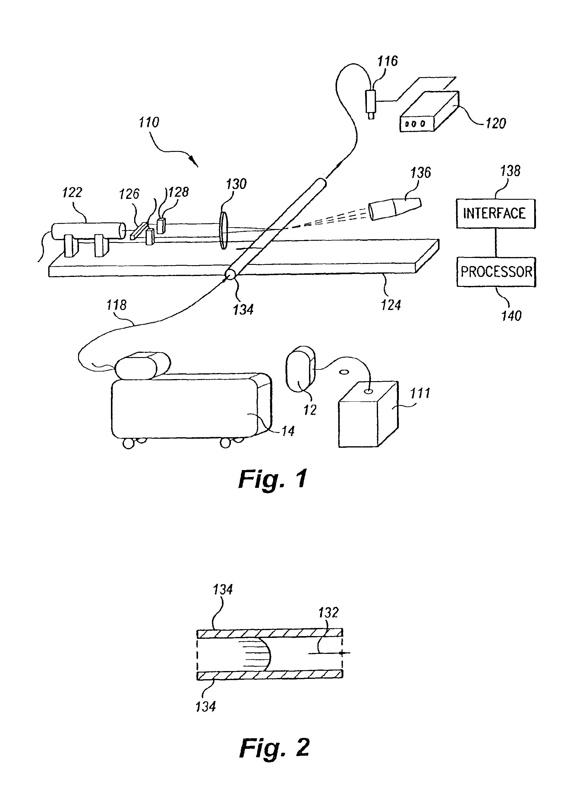
[0017]The stationary stand uses an He—Ne laser focused through a beam splitter to produce two coherent beams which are focused to intersect in the capillary pipe, which is mounted on an optical bench. The forward scatter is detected by a photomultiplier tube, which outputs the detected current to an interface board which may be mounted in a personal computer. Fluid flow is provided by a fuel system having a high pressure pump which is triggered to provide injection pulses to a swirl fuel injector at a predetermined or controllable frequency. The instantaneous and integral mass rates permit the testing, calibration, and setup of optimal characteristics of a fuel injection system and fuel injectors.
[0018]The portable flow meter uses a laser diode focused to reflect the beam through a prism and a holographic splitter which provides two beams focused to intersect in the control measurement zone of the capillary pipe. The capillary pipe is mounted in-line in a motor vehicle's fuel line. Forward scatter is focused on a PIN diode. The interface and electronic data processing system may be the same as that used in the stationary stand embodiment. The use of semiconductor components renders the portable flow meter compact and lightweight for transport, and adaptation of the capillary pipe for insertion into the vehicle's fuel line provides dynamic, in situ diagnostic test, calibration, and setup data for optimal adjustment of the vehicle's fuel injection system.
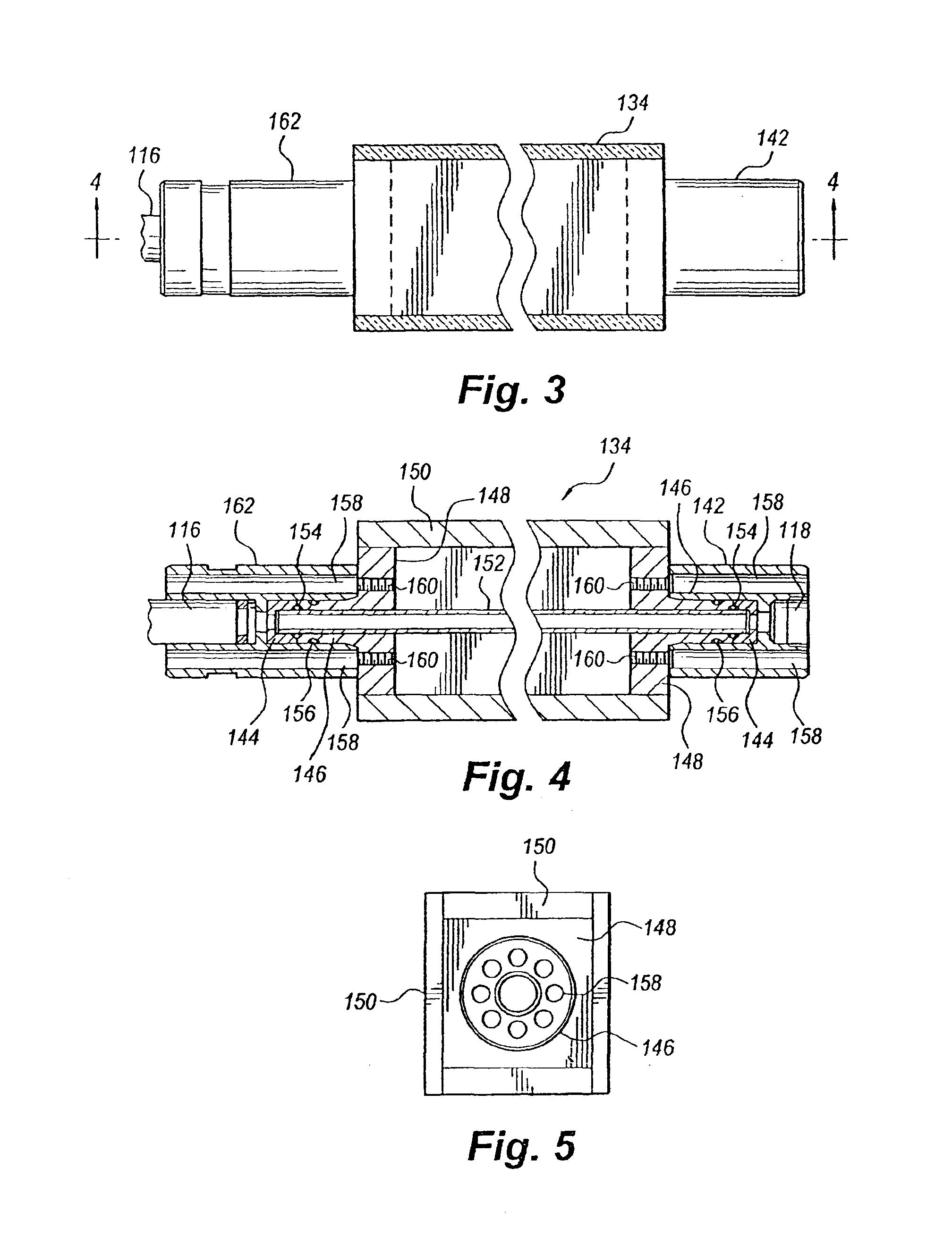
[0019]The on-board sensor has essentially the same optical components as the portable flow meter, except that the beam from the laser diode is not reflected through a prism, but focused directly through an optic wire normal to the capillary pipe. The capillary pipe is encased in a steel sheathe, so that the sensor may be permanently installed in the vehicle's fuel pipeline. The PIN diode detector is connected through an interface to the vehicle's engine control module, and the module's processor executes the data processing software, integrating the flow meter sensor's input with other sensor data to control and adjust injection system characteristics to provide fuel economy, power increase, and reduced exhaust emissions.
[0021]It is another object of the invention to provide a portable, compact, lightweight flow meter capable of connection into a vehicle's fuel line which provides data on transient high pressure fuel injection system characteristics for testing, calibration and setup of optimal fuel injection system parameters.
[0022]It is a further object of the invention to provide an on-board fuel meter sensor connected to a gasoline or diesel engine control module for providing measurement, calculation, and control of transient fuel injection characteristics in order to improve fuel economy, increase engine power, and reduce harmful or noxious exhaust emissions.
[0024]It is an object of the invention to provide improved elements and arrangements thereof for the purposes described which is inexpensive, dependable and fully effective in accomplishing its intended purposes.

Problems solved by technology

Further, no processing means for computing volumetric flow rate is described, and no means for indicating the direction of the velocity is described.

Method used


Image

  • Flow meter
  • Flow meter
  • Flow meter

Examples


Embodiment Construction

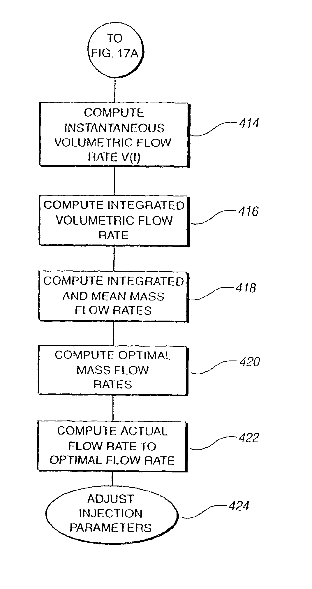
[0045]The present invention is a flow meter for measuring the instantaneous center line velocity in a pipe which uses an electronic data processing method to compute instantaneous and / or integral volumetric and mass flow rates, as well as other transient flow characteristics, from the velocity data by an exact solution of the Navier-Stokes equations for any periodically oscillating fluid flow in a pipe. The embodiments of the flow meter described herein are particularly adapted for measuring flow rates in a high pressure fuel injection system, although it will be obvious to those skilled in the art that the devices and principles described herein are easily modified for applications in industry, pharmacology and medicine.

[0046]Each embodiment of the flow meter includes a laser-Doppler anemometer (LDA) for measuring the center line instantaneous velocity of fluid flow through a capillary measurement pipe, and data processing software for computing flow rates from the measured velocit...


PUM


Abstract

The flow meter is a device having a laser Doppler anemometer (LDA) which measures the instantaneous center line velocity of fluid flow in a pipe and processes the instantaneous velocity so obtained to compute the volumetric flow rate, mass rate, and other flow characteristics as instantaneous quantities and / or integrated over a time interval using an electronic processing method which provides an exact solution to the Navier-Stokes equations for any periodically oscillating flow. The flow meter is particularly adapted for measuring the flow characteristics of high pressure automotive fuel injection systems. Three embodiments of the flow meter are described, including a stationary stand for off-line bench testing flow rate in a fuel injection system, a portable flow meter for inline testing in a vehicle's fuel line, and an on-board flow meter sensor connected to an engine control module.

Description

CROSS-REFERENCE TO RELATED APPLICATIONS[0001]This is a divisional application of U.S. Ser. No. 09 / 854,561, filed May 15, 2001, now U.S. Pat. No. 6,510,842, which is a continuation-in-part of Ser. No. 09 / 614,381, filed Jul. 3, 2000, now abandoned.BACKGROUND OF THE INVENTION[0002]1. Field of the Invention[0003]The present invention relates to flow meters for measuring the flow of fluid through a conduit. The flow meters described are particularly adapted for measuring the volumetric flow rate for a high pressure direct injection automotive fuel injection system. Also described is a software method of determining the volumetric flow rate for a periodic oscillating flow in a pipe from measurement of the instantaneous center line velocity.[0004]2. Description of the Related Art[0005]In automotive fuel injection systems, the power delivered by the engine is related to the shape of the spray, as well as the quantity and timing of fuel delivered to the combustion chamber. The design of fuel...

Claims


Application Information

Patent Timeline
Patent Type & Authority Patents(United States)
IPC IPC(8): F02M61/00F02M61/16F02M65/00F02M55/02F02M61/18F02M63/00F02D41/40F02M51/06G01F1/66G01F1/86G01F1/76F02B75/12F02B75/00
CPCF02D41/40F02M51/0678F02M55/02F02M61/163F02M61/18F02M63/00F02M65/00G01F1/661G01F1/86F02B2075/125F02D2041/288F02D2041/389F02D2200/0614F02M2200/24Y02T10/44Y02T10/123Y02T10/12Y02T10/40
Inventor ISMAILOV, MURAD M.
Owner COMBUSTION DYNAMICS
Learn More