Dynamotor driven compressor and method for controlling the same

a compressor and dynamotor technology, applied in the direction of positive displacement liquid engines, liquid fuel engines, piston pumps, etc., can solve the problems of large weight of the pulley for receiving the power from the internal combustion engine, complicated control operation, and vehicle occupants to feel uncomfortable, so as to reduce the size and weight, simplify the structure, and reduce the cost

Inactive Publication Date: 2005-09-06
DENSO CORP +1
View PDF16 Cites 42 Cited by
  • Summary
  • Abstract
  • Description
  • Claims
  • Application Information

AI Technical Summary

Benefits of technology

[0021]The use of the dynamotor of magnet type having at least a permanent magnet simplifies the structure, and therefore makes it possible to manufacture a compact, lightweight dynamotor at a lower cost. This is also true in the case where the dynamotor is incorporated in a driven pulley on the side of the compressor

Problems solved by technology

When this system is used, as long as the vehicle is stationary, the compressor of the air-conditioning system of the particular vehicle also stops and the air-conditioning system is turned off, thereby causing the vehicle occupants to feel uncomfortable.
The first well-known example of the hybrid compressor poses the problems that a swash-plate compressor of a variable displacement type having a complicated structure is used to make the discharge capacity variable, that the motor is only an auxiliary drive source for driving the compressor temporarily while the internal combustion engine is out of operation and is useless in other points, that a complicated control operation is required in spite of the rather poor functions and effects, and that the pulley for receiving the power from the internal combustion engine is very bulky because the electromagnetic clutch and the motor are built inside of the pulley.
On the other hand, the problems of the second well-known example of the hybrid compressor are t

Method used


Image

  • Dynamotor driven compressor and method for controlling the same
  • Dynamotor driven compressor and method for controlling the same
  • Dynamotor driven compressor and method for controlling the same

Examples


first embodiment

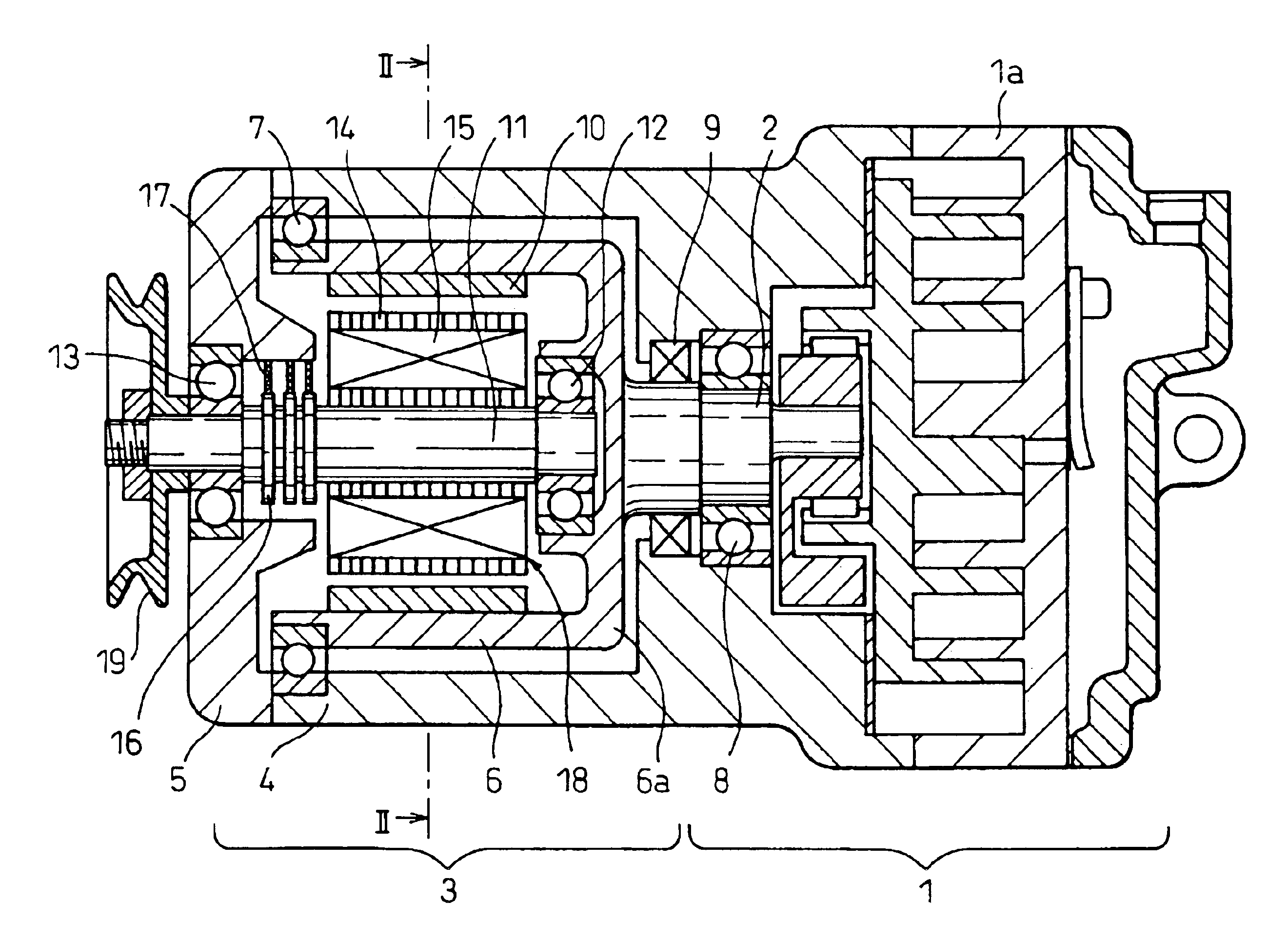
[0043]A composite drive system for a compressor according to the invention will be explained with reference to FIGS. 1 to 6. As is apparent from FIG. 1, showing a longitudinal sectional view of the essential parts, a compressor 1 to be driven by the system is a scroll compressor having a well-known structure. Especially, this embodiment employs a compressor of fixed displacement type having no mechanism therein for changing the discharge capacity per rotation. The compressor 1 may be of a type other than a scroll compressor. The structure and operation of the scroll compressor are well known, and therefore will not be explained below. In short, the compressor 1 has a single drive shaft 2 for receiving the motive power and, when the drive shaft 2 is rotationally driven, it can compress a fluid such as a refrigerant circulated through the refrigeration cycle of an automotive air-conditioning system.

[0044]The discharge capacity per rotation of the compressor 1 may be normally about one...

fifth embodiment

[0091]These coils 15 are supplied, through wiring not shown, with the three-phase AC power from the inverter in the power control unit 25 shown in FIG. 15 to thereby generate a rotary magnetic field on the iron core 53. The inverter is supplied with the DC power from the battery 24. The rotary magnetic field of the iron core 53 rotates the rotor 52 having the permanent magnets 10, thereby rotationally driving the drive shaft 2 of the compressor 1. This is the operation in motor mode of the dynamotor 3 according to the In this case, the coils 15 are fixed together with the iron core 53, and therefore, as in each of the embodiments described above, the need is eliminated of the power feeding mechanism including the slip rings or the commutator and the brushes for supplying power to the coils 15.

[0092]A dish-shaped hub 55 is mounted on the rotary shaft 11 of the dynamotor 3 through a one-way clutch 54. The grease for lubricating the one-way clutch 54 is sealed hermetically in the cyli...


PUM


Abstract

A dynamotor capable of operating as either a motor or a generator is used with both the armature portion and the field portion thereof capable of being rotated. In the case where a pulley operatively interlocked with the output shaft of the prime mover is mounted on the rotary shaft of the armature portion, the drive shaft of the compressor is mounted on the rotating field portion. Once the dynamotor is operated in motor mode, the rotational speed of the compressor is increased to the sum of the input rotational speed and the rotational speed of the dynamotor. The compressor is stopped by disconnecting a power feed circuit. When the input rotational speed is too high, the dynamotor is operated in generator mode. In this way, the rotational speed is reduced in accordance with the generated electric energy.

Description

CROSS-REFERENCE TO RELATED APPLICATION[0001]This application is a Continuation Application of U.S. patent application Ser. No. 10 / 074,242, filed on Feb. 14, 2002 now U.S. Pat. No. 6,659,738, which in turn is related to and claims priority from Japanese Application Serial Number 2001-038589, filed Feb. 15, 2001, the contents of both applications being incorporated by reference.BACKGROUND OF THE INVENTION[0002]1. Field of the Invention[0003]The present invention relates to a composite drive system, for a compressor, capable of rotationally driving the compressor selectively or at the same time by either of two drive sources including a prime mover such as an internal combustion engine and a motor rotated by the power of a battery.[0004]2. Description of the Related Art[0005]To cope with the environmental problems in recent years, the practical application of an idle-stop (or “eco-run”) system has been promoted for stopping an internal combustion engine when a vehicle such as an automo...

Claims


Application Information

Patent Timeline
IPC IPC(8): F04B35/00F04C18/02F04B35/04F04C29/00F04B27/08F02D29/04F02D29/06F04B49/06F04C23/00F04C23/02H02K7/14H02K7/18H02K21/22
CPCF04B27/0895F04B35/04F04C18/0215F04C29/0064F04C29/0085F04C2240/45F04C2240/50
Inventor IWANAMI, SHIGEKIOGAWA, YUKIOINOUE, TAKASHIASA, HIRONORI
Owner DENSO CORP
Why Eureka
Try Eureka