Spatially-arranged chemical processing station

a chemical processing station and spatial arrangement technology, applied in the direction of liquid surface applicators, coatings, electrical devices, etc., can solve the problems of reducing system reliability, smallest equipment size, and reducing cost, so as to reduce floor area, high interconnect density, and high production efficiency

Inactive Publication Date: 2005-09-06
LAM RES CORP
View PDF6 Cites 10 Cited by
  • Summary
  • Abstract
  • Description
  • Claims
  • Application Information

AI Technical Summary

Benefits of technology

[0014]It is an object of the present invention to provide a processing station that contains a plurality of individual and independently operating processing chambers arranged in mutiple-level manner vertically and in linear rows horizontally with transfer of objects by means of by a common workpiece handling unit. It is another object is to provide the aforementioned station suitable for electroless deposition in the mass production of semiconductor wafers with high interconnect density. A further object is to provide the aforementioned station which is universal in use, flexible for restructuring in accordance with specific production requirements, highly efficient in production due to parallel

Problems solved by technology

The new system configuration results in the smallest possible equipment size for a relatively slow process than

Method used


Image

  • Spatially-arranged chemical processing station
  • Spatially-arranged chemical processing station
  • Spatially-arranged chemical processing station

Examples


Embodiment Construction

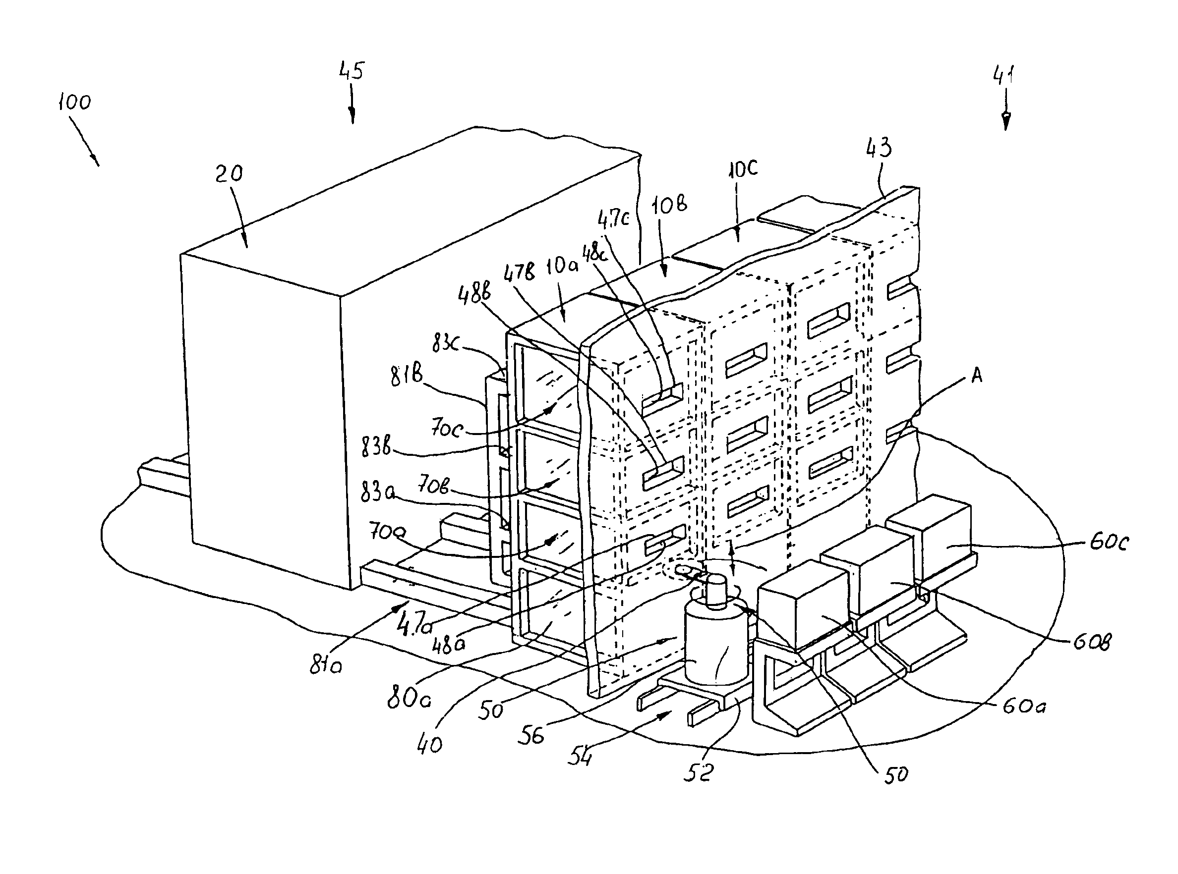
[0030]This invention discloses an equipment configuration which is both novel and flexible, for the electroless deposition of copper, a passivation layer, and a barrier layer. The apparatus consists of a number of processing modules and each module in turn comprises a number of process chambers. At least one of the chambers is capable of depositing thin metal films by electroless means. All necessary processing steps for film deposition are performed in a single processing chamber. Thus, the unit provides a way of reducing the number of times the wafer needs to be transferred between wet steps.

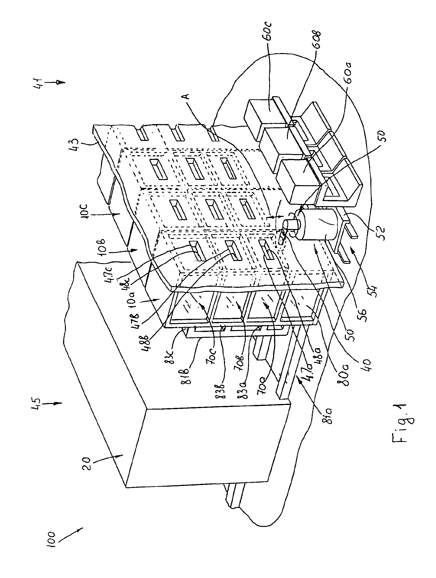
[0031]Reference is made to FIG. 1, which is a three-dimensional general view of a single-wafer electroless deposition station (hereinafter referred to as “system”) of this invention. The system is designated as a whole by the reference numeral 100. The system consists of a multiple number of processing modules 10a, 10b, 10c, etc arranged in a line in a horizontal manner (only three of them are...


PUM


Abstract

The present invention discloses a station, e.g., for IC fabrication with a flexible configuration. It consists of an array of processing chambers, which are grouped into processing modules and arranged in a two-dimensional fashion, in vertical levels and horizontal rows, and is capable of operating independent of each other. Each processing chamber can perform electroless deposition and other related processing steps sequentially on a wafer with more than one processing fluid without having to remove it from the chamber. The system is served by a single common industrial robot, which may have random access to all the working chambers and cells of the storage unit for transporting wafers between the wafer cassettes and inlet/outlets ports of any of the chemical processing chambers. The station occupies a service-room floor space and a clean-room floor space. The processing modules and the main chemical management unit connected to the local chemical supply unit occupy a service-room floor space, while the robot and the wafer storage cassettes are located in a clean room. Thus, in distinction to the known cluster-tool machines, the station of the invention makes it possible to transfer part of the units from the expensive clean-room area to less-expensive service area.

Description

FIELD OF THE INVENTION[0001]The present invention relates to semiconductor manufacturing equipment. More particularly, the invention relates to a spatially-arranged station for deposition from liquid media, e.g, to an electroless deposition station that contains a plurality of individual and independently operating chemical processing chambers served by a common workpiece handling unit. The station of the present invention may find use in the mass production of high density interconnect for integrated circuits.BACKGROUND OF THE INVENTION[0002]In present ULSI (ultra-large-scaled-integration) structures, high circuit speed, high packing density and low power dissipation are essential. As a result, feature sizes must be scaled downward, and the interconnect related time delays become the major limitation. Elemental aluminum and its alloys have been the traditional metals used to form lines and plugs in IC's; however, aluminum has a relatively high resistivity and its electromigration s...

Claims


Application Information

Patent Timeline
IPC IPC(8): H01L21/00H01L21/677
CPCH01L21/67017H01L21/67173H01L21/67178H01L21/67769
Inventor IVANOV, IGORTING, CHIUZHANG, JONATHAN WEIGUOKOLICS, ARTHUR
Owner LAM RES CORP
Why Eureka
Try Eureka