Graphite particles and process for production thereof

a technology of graphite particles and graphite, which is applied in the direction of sustainable manufacturing/processing, cell components, and final product manufacturing, can solve the problems of scaly graphite particles obtained by grinding, and achieve the effects of high crystallinity of graphite, easy production, and excellent properties of highly crystalline graphi

Inactive Publication Date: 2005-09-06
NIPPON POWER GRAPHITE CO LTD
View PDF9 Cites 15 Cited by
  • Summary
  • Abstract
  • Description
  • Claims
  • Application Information

AI Technical Summary

Benefits of technology

[0019]All of these crushers or mills can give a strong shear force, a strong compression force and a strong impact and therefore can grind graphite in a short time. In many cases, however, the graphite particles obtained by grinding are scaly.
[0022]The inner construction of each scaly graphite particle is simple when observed by an electron microscope. When the graphite section vertical to the AB planes of graphite is observed, it is appreciated that the streaks showing a laminate structure are always linear and each scaly graphite particle is a laminate of plate-like graphite layers.
[0038]The graphite particles of the present invention have each a bent laminate structure inside and a nearly spherical shape and, therefore, have anisotropy per se. Consequently, various molded materials produced from these graphite particles are unlikely to give rise to orientation. When the present graphite particles are used, for example, as an electrode material, an electrode of small electric resistance can be produced. Further, since the present graphite particles retain the high crystallinity of graphite, a graphite molded material retaining the excellent properties of highly crystalline graphite can be obtained from the present graphite particles.
[0039]According to the present process for producing graphite particles, graphite particles having a bent laminate structure can be easily produced by using a widely used impact grinder.

Problems solved by technology

In many cases, however, the graphite particles obtained by grinding are scaly.

Method used


Image

  • Graphite particles and process for production thereof
  • Graphite particles and process for production thereof
  • Graphite particles and process for production thereof

Examples


example 1

[0094]Graphite particles produced in China, having an average particle diameter of 3.3 mm in the AB plane direction and a lattice constant Co (002) of 0.6707 nm were used as a raw material graphite. A pin mill produced by Leche Co. was used as a grinder. When the rpm of the rotor of the pin mill reached 20,000, the raw material graphite was fed at a rate of 200 g / min by allowing the graphite to be carried by the suction wind generated by the grinder.

[0095]The outermost rotating pins were arranged on a circumference of 9.5 cm in diameter and their linear speed was about 100 m / sec.

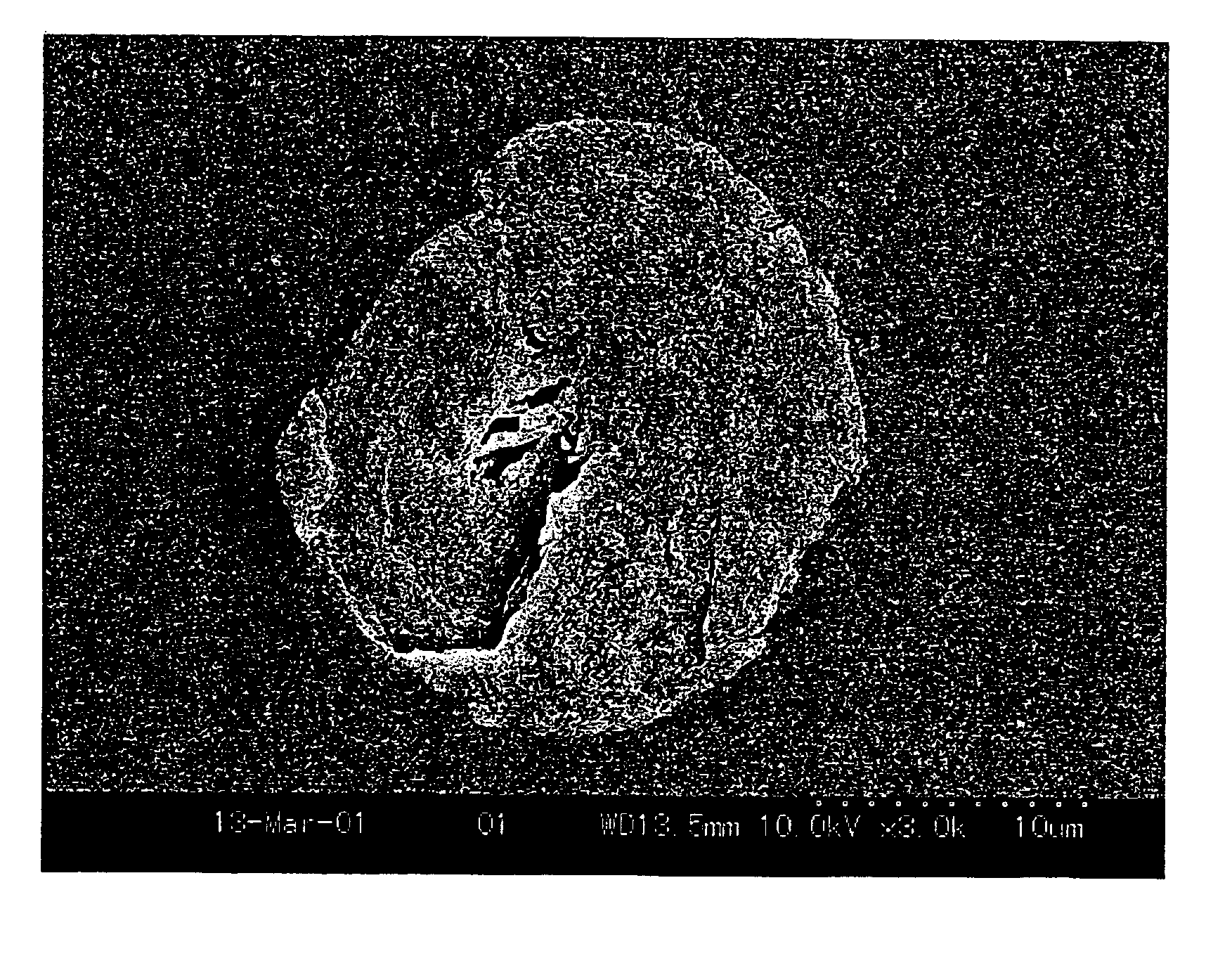
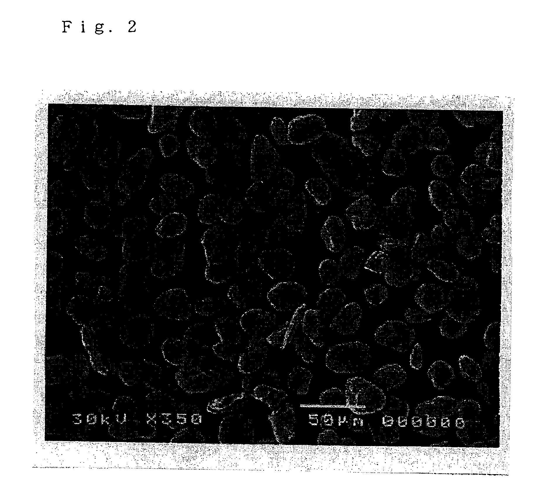
[0096]The ground graphite particles were collected by a cyclone and a bag filter. The collected graphite particles were again fed into the grinder by allowing them to be carried by the above suction wind. This grinding operation was repeated 20 times in total to obtain spherical graphite particles.

[0097]The graphite particles obtained had the following properties.[0098]Average particle diameter: 25.6 μm[0099...

example 2

[0121]Graphite particles produced in Brazil, having an average particle diameter of 0.3 mm in the AB plane direction and a lattice constant Co (002) of 0.6708 nm were used as a raw material graphite. As a grinder, there was used the same pin mill (produced by Leche Co.) as used in Example 1 except that the rotor (pin rotor) of the pin mill was changed to an edge rotor having triangular teeth.

[0122]The triangular teeth were arranged coaxially with the edges directed to the center of the rotor and with each two adjacent triangular teeth of the outermost circumference being apart so as to form a gap of 2 mm. The diameter of the outermost circumference was 8.0 cm. In ordinary grinding, a strainer is provided near the circumference of the rotor; however, no strainer was provided in this Example.

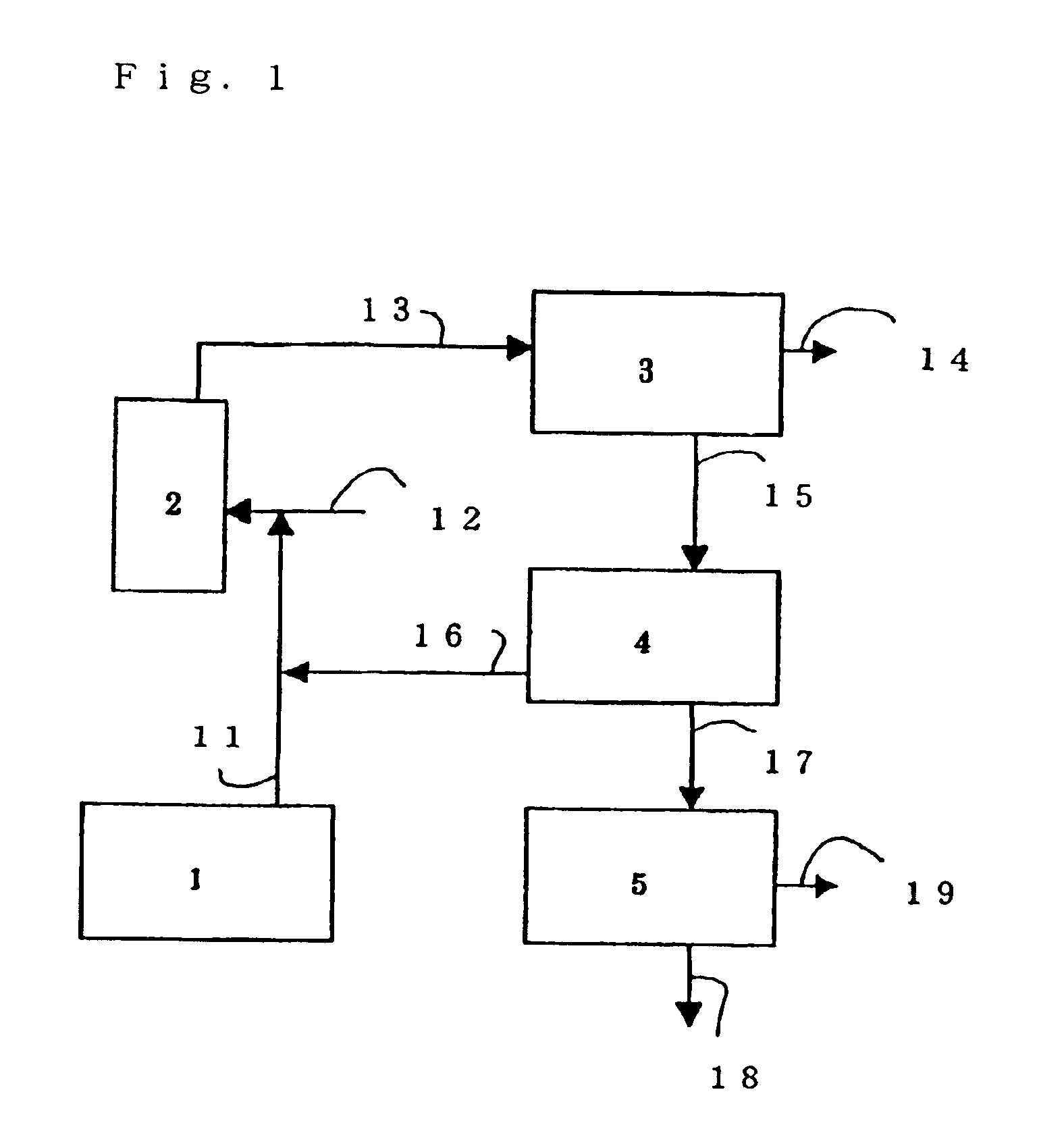
[0123]The inlet and the outlet of the pin mill were connected to each other by a pipe. Thereby, the air current generated by the rotation of the rotor is returned from the outlet to the inlet via ...

application example 1

[0131]400 g of the spherical graphite particles obtained in Example 1 and 200 g of a novolac type phenolic resin (melting-starting temperature: 95° C.) produced by Gunei kagaku Kogyosha were placed in a Henschel mixer, 10 B produced by Mitsui Mining Co., Ltd. The agitating blades of the mixer were rotated at 3,200 rpm for 10 minutes to conduct mixing and kneading. During this period, the sample temperature increased from room temperature to 120° C.

[0132]Then, cooling was made and the mixer rotation was decreased to 1,600 rpm, and agitation was made at 110° C. for 2 minutes to obtain granules having an average particle diameter of about 100 μm.

[0133]The granules were molded at 200° C. at 10 MPa using a press, PY-50EA produced by Kodaira Seisakusho, to obtain a molded material of 120×100×1 mm for fuel cell separator. The molded material had a density of 2.00 g / cc, a three-point bending strength of 62 MPa as measured by JIS K 6911-1979, a contact resistance of 2.0 Ω·cm2, and a helium l...


PUM

PropertyMeasurementUnit
particle diameteraaaaaaaaaa
lattice constantaaaaaaaaaa
particle diameteraaaaaaaaaa

Abstract

Graphite particles having a bent laminate structure inside each particle are produced by feeding, into an impact grinder, graphite particles having an average particle diameter of 5 mm or less together with a gas current to apply an impact to the graphite particles to form, by a compression force, a bent laminate structure inside each graphite particle. The resulting graphite particles have an average particle diameter of 100 μm or less, are low in anisotropy, have a nearly spherical shape, and are highly crystalline.

Description

BACKGROUND OF THE INVENTION[0001]1. Field of the Invention[0002]The present invention relates to nearly spherical graphite particles suitably used as an anode material for lithium secondary battery, a separator material for fuel cell, etc., as well as to a process for production thereof.[0003]2. Description of the Prior Art[0004]Graphite particles have found wide applications as an anode material for lithium secondary battery, a separator material for fuel cell, etc. The raw materials for the graphite particles used in such applications are natural graphite and artificial graphite.[0005]Graphite particles obtained by grinding natural graphite show striking anisotropy in particle shape, owing to the crystal structure. The particle shape of such graphite particles is scaly (plate-like). That is, the crystals of the graphite particles have a structure constituted by a number of large AB planes laminated in the C axis direction. Since each AB plane has a large area while the laminate th...

Claims


Application Information

Patent Timeline
Patent Type & Authority Patents(United States)
IPC IPC(8): C01B31/00C01B31/04H01M4/58H01M8/02H01M4/587H01M10/05
CPCC01B31/04H01M4/587H01M8/0213H01M8/0226C01P2002/77C01P2004/54C01P2004/61C01P2006/11C01P2006/40Y02E60/50C01B32/21Y02P70/50Y02E60/10
Inventor FUKUDA, KENJITSUNAWAKI, TADANORIUMENO, TATSUOMURAYAMA, KOHEIHARA, YOUICHIRO
Owner NIPPON POWER GRAPHITE CO LTD
Why Eureka
Try Eureka