
Growth media wastewater treatment reactor

a growth media and wastewater treatment technology, applied in the direction of multi-stage water/sewage treatment, filtration separation, separation process, etc., can solve the problems of inefficient oxygen absorbing device, insufficient oxygen supply in the device, and not directly providing oxygen to the device, so as to achieve adequate circulation in the system and increase the effect of oxygen transfer

Inactive Publication Date: 2005-09-13
DELTA TREATMENT SYST LLC
View PDF23 Cites 43 Cited by
  • Summary
  • Abstract
  • Description
  • Claims
  • Application Information

AI Technical Summary

Benefits of technology

[0016]It is an object of the invention to provide an aerated wastewater system using growth media

Problems solved by technology

However, in these devices, oxygen is not directly transferred to the growing biomass on the growth media, but only indirectly and inefficiently through oxygen absorbed in wastewaters (dissolved oxygen) transferred during the air lift operation.
This device does not provide oxygen directly through the media, and hence, still suffers from clogging (See U.S. Pat. No. 6,105,593 to MacLaren, et al, describing a cleaning probe for the '524 device) and is not as efficient in providing oxygen directly to the growing biomass.
Additionally, the McDonald device is a series of tanks substantially filled with media: the McDonald device lacks a media free treatment volume (a buffer zone or dilution zone).
This lack results in the need for an excessive amount of media to effect treatment, making the McDonald device inefficient and uneconomic.
Additionally, the lack of a dilution or buffer zone in each reactor chamber makes treatment inefficient.
With higher concentration of solution sludge, treatment is more inefficient as the ration of usable (digestible) waste materials to total waste materials is suppressed.
Reduced upward turbulence in the growth media increases the potential for bacterial growth to occlude the channels, thereby plugging or clogging the flow channels in the media.
This process, however, dilutes the raw incoming sewage or wastewater and extends the time for materials present in the incoming waters to be transported to the treatment media.
Two of the plant performance characteristics that fixed growth media treatment plants have difficulty achieving are start-up time and vacation time.
The regulatory requirement for start-up / vacation times are difficult to achieve for growth media surfaces as the biomass on the growth surfaces must either be established (for start-up) or replenished after a period of starvation (during the dormant period).
Consequently, a growth media treatment system will take longer to start-up than an extended air treatment system.

Method used


Image

  • Growth media wastewater treatment reactor
  • Growth media wastewater treatment reactor
  • Growth media wastewater treatment reactor

Examples


Embodiment Construction

A. The Treatment System—Retrofit

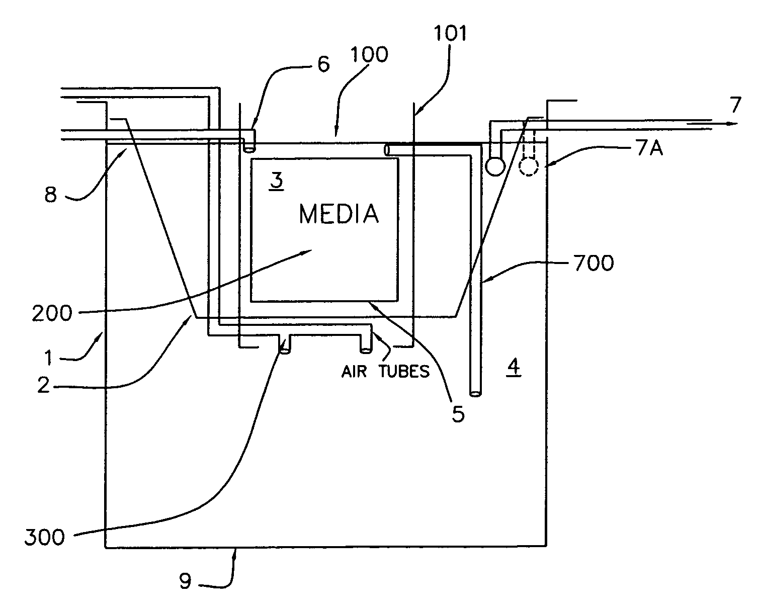
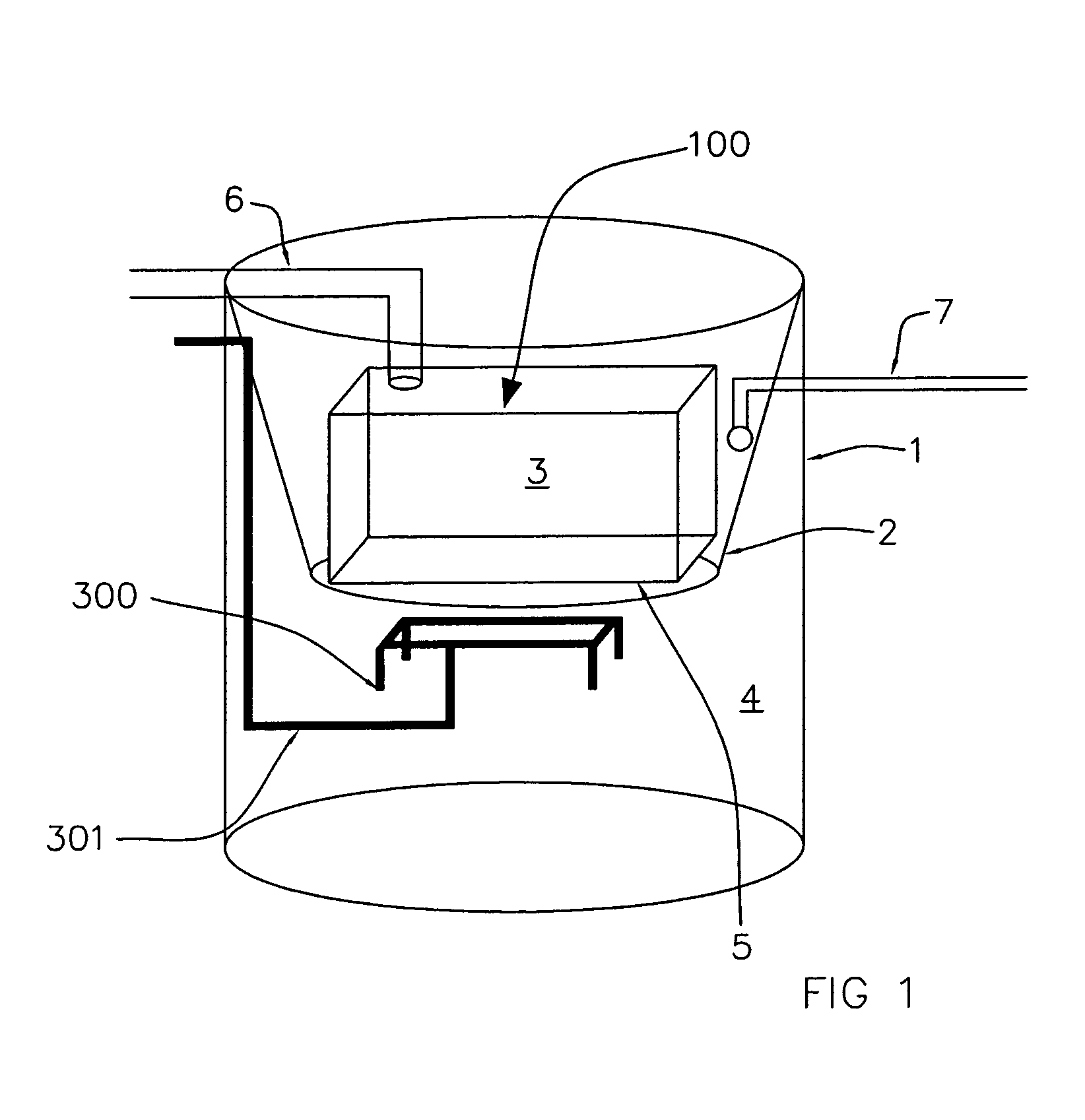
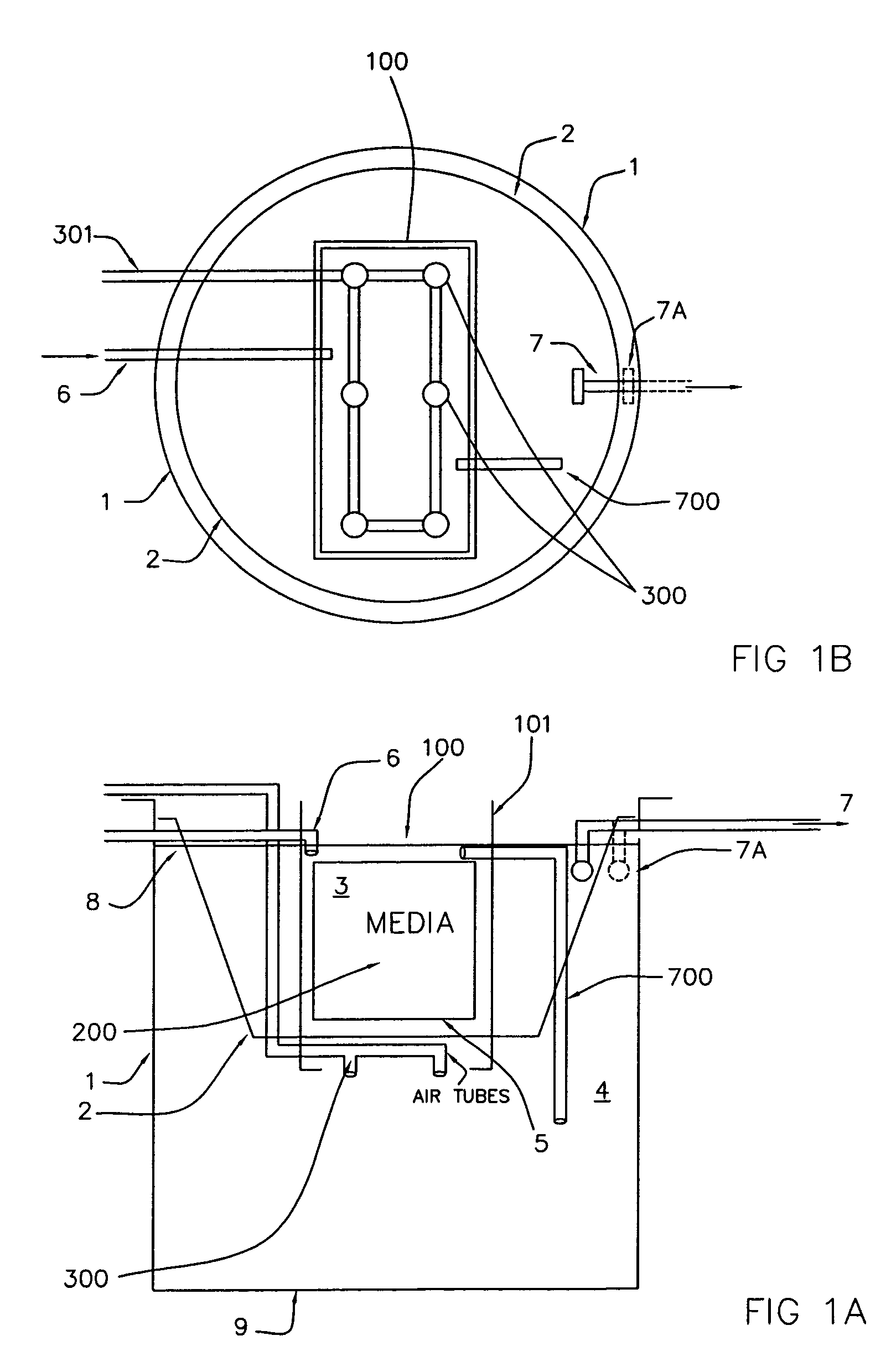
[0040]Shown in FIG. 2 is a prospective view of a prior art Hansel system, showing a tank 1, a sidewall 2 creating an internal volume considered the clarifier (also called the quiescent zone). The volume external to the clarifier area contains a series of discrete air release sites 300, connected by an air distribution manifold 301 to an air compressor. The volume external to the clarifier area is considered the mixing zone. Wastewaters are brought into the mixing zone through an inlet 6, and removed from the system through outlet 7 positioned in the clarifier. FIG. 1 shows a Hansel-type treatment system modified for incorporation in the present invention. Shown is tank 1, having a closed bottom and closable top, and is generally constructed of resin reinforced fiberglass. Positioned within the tank 1 is the clarifier sidewall 2. As shown, tank 1 is a cylinder with clarifier sidewall 2 forming a second cylinder (the clarifier) having an open bottom and...


PUM

PropertyMeasurementUnit
Angleaaaaaaaaaa
Flow rateaaaaaaaaaa
Areaaaaaaaaaaa

Abstract

A reactor chamber for placement in a wastewater treatment system, where the reactor chamber has a chamber formed from a sidewall which forms an interior of the chamber. The sidewall has a top portion and a bottom portion and fixed channel growth media positioned in the interior of the chamber. The fixed channel growth media is positioned below the top of the sidewall, so that when positioned in a treatment system, most of the growth media is located below the water level in the treatment system. The top of the sidewall near the water level (when positioned in a treatment system) is substantially impermeable to wastewater. The reactor includes an air distribution manifold system having a series of air release sites positioned below the fixed channel growth media and adapted to release air which disperses upwardly through the fixed channel growth media.

Description

BACKGROUND OF THE INVENTION[0001]1. Field of the Invention[0002]The invention relates to wastewater processing reactors, and in particular, to aerated fixed channel growth media reactors.[0003]2. The Prior Art[0004]Aerated wastewater treatment systems designed for small applications (less than 50,000 gallon daily capacity) generally involve an aeration treatment chamber or zone for injecting air into the wastewater, and a clarifier chamber of zone, a quiescent zone in which particles are allowed to settle out of the system. An example of such a treatment chamber is shown in Hansel. As can be seen, the aeration treatment zone is generally an empty chamber having several air release sites, usually located at the bottom of the chamber. An aerated treatment system treats wastewater through aerobic bacterial degradation of the waste materials present in wastewater or sewage. Aerobic bacterial metabolic degradation requires dissolved oxygen and hence, the release of air into the treatment...

Claims


Application Information

Patent Timeline
IPC IPC(8): C02F3/06
CPCC02F3/101C02F3/1247Y02A20/208Y02W10/10
Inventor COX, RALEIGH LEECOX, CHRISTOPHER EDWARDGUY, BRENDACATANZARO, MICHAEL DAVIDARCEMONT, III, MURPHY MARTINLEJEUNE, TRAVIS LEE
Owner DELTA TREATMENT SYST LLC
Learn More