Data transfer control circuit with terminal sharing

a control circuit and terminal technology, applied in the field of dma (direct memory access) data transfer technology, can solve the problems of dma transfer processing slowdown, system complexity and cost increase, and overrun, so as to prevent termination of dma transfer, reduce the number of terminals, and increase system throughput

Inactive Publication Date: 2005-09-13
RENESAS ELECTRONICS CORP
View PDF4 Cites 28 Cited by
  • Summary
  • Abstract
  • Description
  • Claims
  • Application Information

AI Technical Summary

Benefits of technology

[0011]According to the above described means, peripheral devices to make DMA transfer requests can get in advance the states of the request queues, so that an underrun and overrun can be avoided without provision of a circuit such as a counter for counting an output count of DMA transfer requests. If the system is configured so that the states of the queues are outputted from the above described external terminal by a signal produced by encoding a signal indicating the state of each stage of the queues, and is outputted in time-sharing mode, using an external terminal shared with an external terminal for outputting channel identification information, the number of terminals can be reduced.
[0012]A second invention of the present patent application is a data transfer control circuit that controls data transfers between a memory and peripheral circuits or peripheral devices without involvement of a central processing unit, wherein data transfer control can be performed with respect to plural channels, queues capable of holding the identification information of plural channels concerned in data transfer requests are provided, and the contents of the queues can be cleared.
[0013]According to the above described means, DMA transfer processing can be performed without retrying the setting of control registers and the queues can be cleared without performing unnecessary DMA transfers. As a result, system throughput is increased. Also, without providing a circuit such as a counter for counting an output count of DMA transfer requests, to peripheral devices as DMA transfer request sources, termination of DMA transfers is prevented with transfer requests remaining in the queues. This relieves the user of heavy design burden and prevents the system from becoming complicated.
[0014]As a means for clearing the above described queues, for example, an external terminal for inputting a signal for clearing the contents of the queues may be provided. In this case, if the signal for clearing the contents of the queues is inputted in time-sharing mode, using an external terminal shared with an external terminal for inputting a signal requesting a data transfer, the number of terminals can be reduced.

Problems solved by technology

In addition, since a conventional DMA controller is not provided with a function for getting the contents of the request queue, an overrun may have occurred in an attempt by peripheral devices to execute more DMA transfer requests than held in the request queue.
As a result, disadvantageously, a user's design burden becomes greater and the size of peripheral logic circuits becomes larger, so that the system becomes more complicated and costlier.
Accordingly, there has been a problem in that, in continuous execution of DMA transfers, DMA transfer processing slows down because clearing the request queues requires the setting of the control registers to be retried.

Method used


Image

  • Data transfer control circuit with terminal sharing
  • Data transfer control circuit with terminal sharing
  • Data transfer control circuit with terminal sharing

Examples


Embodiment Construction

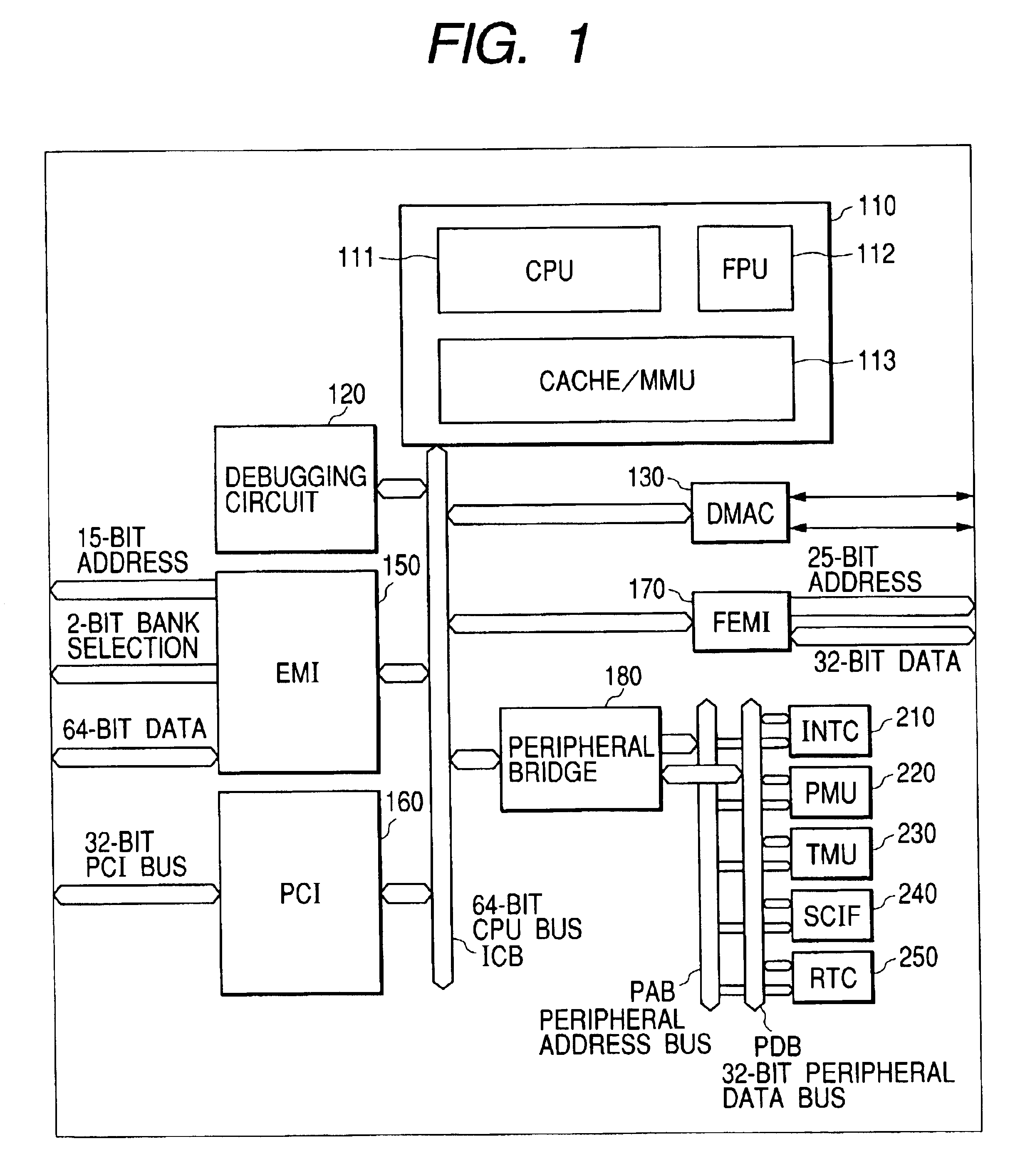
[0028]Hereinafter, preferred embodiments of the present invention will be described with reference to the drawings. FIG. 1 schematically shows the configuration of an embodiment of a microprocessor provided with a DMA controller to which the present invention is applied. Although there is no particular limitation, circuit blocks shown in FIG. 1 are formed on one semiconductor chip such as a monocrystalline silicon by known semiconductor integrated circuit manufacturing technology.

[0029]As shown in FIG. 1, the microprocessor of this embodiment comprises: a control part 110 comprising a central processing unit (CPU) 111 of a program control system that interprets program instructions, performs data operations, and controls the whole chip; a floating point unit (FPU) 112 that performs floating point operations and other operations instead of the CPU; and a cache memory and memory management unit 113 that manages a cache memory used to temporarily store data such as a program executed b...


PUM


Abstract

A DMA controller including a request queue for holding DMA transfer requests clears only the request queue without executing unnecessary DMA transfers and provides information about the states of the queue. A DMA controller is configured to enable data transfer control with respect to plural channels and includes a request queue capable of holding the identification information of channels concerned in plural data transfer requests, wherein the states of the request queue can be outputted and information held in the request queue can be cleared.

Description

BACKGROUND OF THE INVENTION[0001]The present invention relates to DMA (direct memory access) data transfer technology in a microcomputer system and technology effectively applied to a method for controlling queues for temporarily holding DMA transfer requests. It relates to technology effectively used for a DMA (direct memory access) controller or DMA control circuit incorporated in, e.g., a microprocessor or microcomputer.[0002]In a system using a one chip microcomputer including a central processing unit (hereinafter referred to as CPU), and peripheral modules such as a timer circuit and a serial communication interface circuit, a DMA controller is used to enable data to be directly transferred between a memory and peripheral devices without involvement of the CPU. The DMA controller, which is sometimes configured as an LSI distinct from a microcomputer, is recently often incorporated in a microcomputer and microprocessor. Such a DMA controller may be provided with an FIFO (First ...

Claims


Application Information

Patent Timeline
Patent Type & Authority Patents(United States)
IPC IPC(8): G06F13/20G06F13/28
CPCG06F13/28
Inventor NARUSE, TAKANOBUYOSHIOKA, SHINICHINAKAGAWA, NORIO
Owner RENESAS ELECTRONICS CORP
Why Eureka
Try Eureka