Programmable multi-dose intranasal drug delivery device

a drug delivery device and multi-dose technology, applied in the field of programmable intranasal drug delivery devices, can solve the problems of time-consuming and burdensome medical personnel, devices are limited to the control of the administration of liquid pharmaceutical compositions via intravenous, and are expensive to maintain and occupy valuable space, so as to discourage diversion and abus

Inactive Publication Date: 2005-09-27
UNIV OF KENTUCKY RES FOUND
View PDF54 Cites 231 Cited by
  • Summary
  • Abstract
  • Description
  • Claims
  • Application Information

AI Technical Summary

Benefits of technology

[0009]Another object of the invention is to provide an intranasal drug delivery device which provides the administration of a precise volumetric unit dose of a controlled sub

Problems solved by technology

In addition to being expensive, the existing programmable devices and systems for the self-administration of analgesics such as the opioids and other controlled substances are bully, require skilled personnel to set up at the patient's bedside, are expensive to maintain and occupy valuable space, not only in the patient's room but also in the health care facility's store rooms.
These devices are also limited to the control of the administration of liquid pharmaceutical compositions via intravenous (and intra muscular) routes.
In addition to a priming procedure for the pump that is somewhat time-consu

Method used


Image

  • Programmable multi-dose intranasal drug delivery device
  • Programmable multi-dose intranasal drug delivery device
  • Programmable multi-dose intranasal drug delivery device

Examples


first embodiment

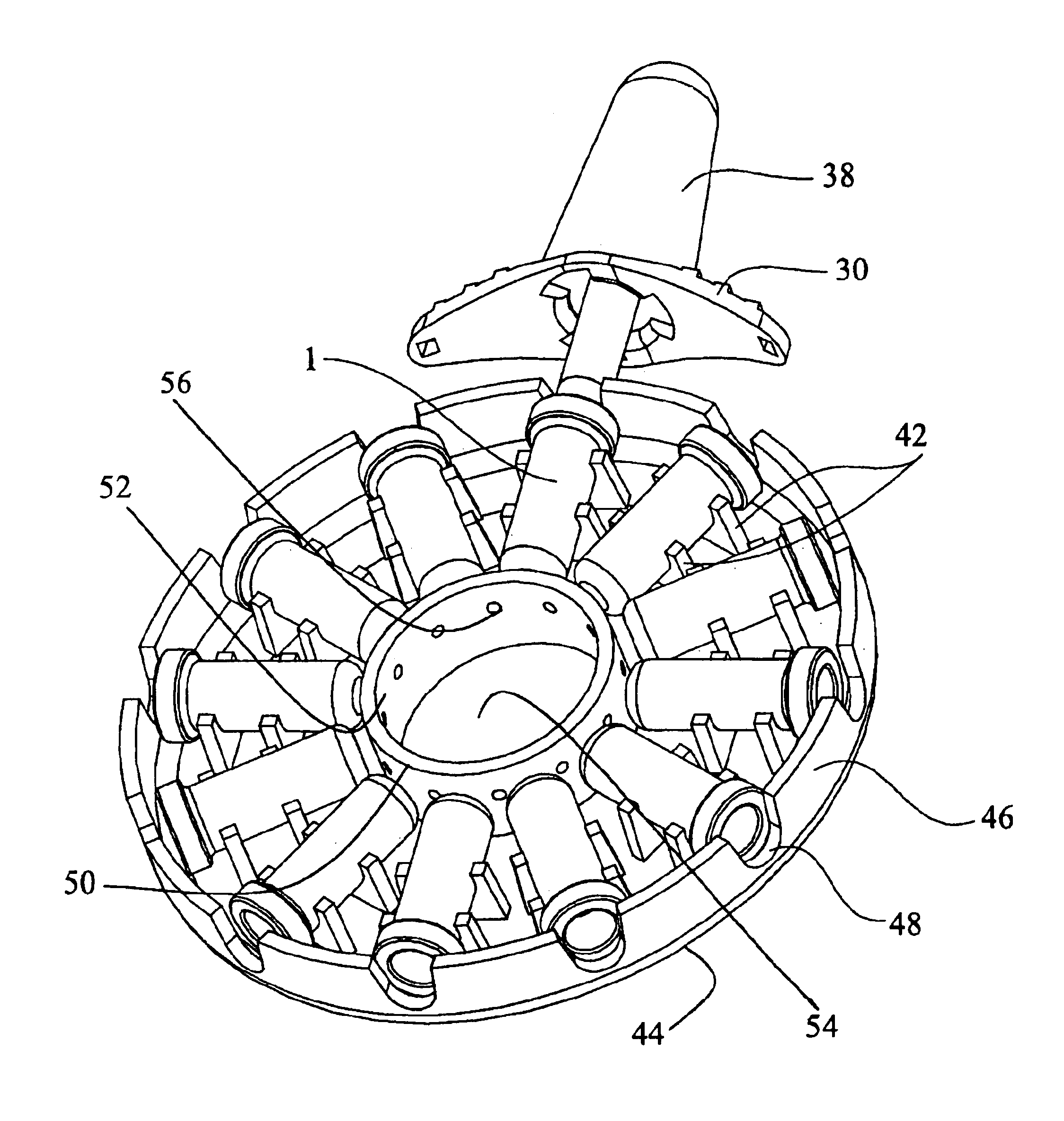
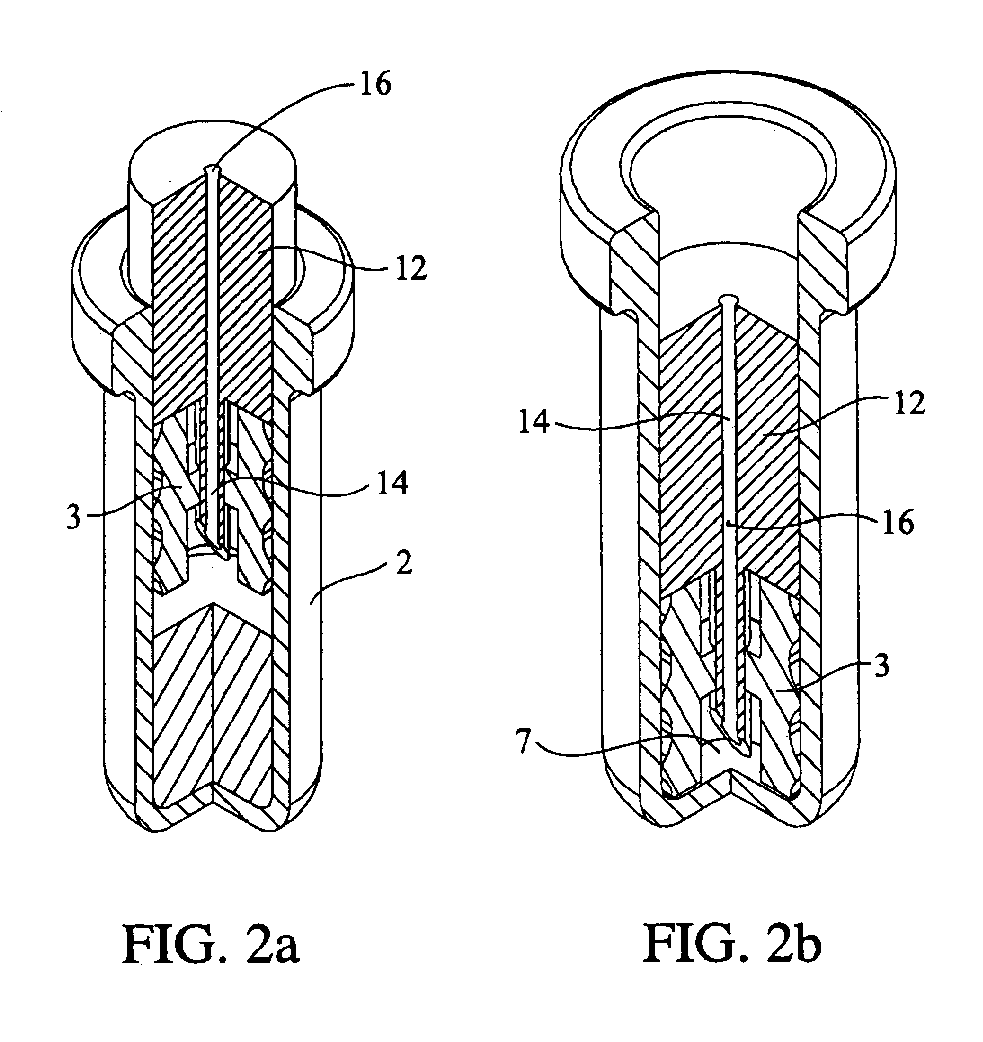
[0090]In another preferred embodiment which will be described with reference to FIGS. 17, 18 and 19, the pivotally-mounted escapement control arm 120 is actuated by a force resulting indirectly from the passage of an electrical current through a length of nitinol wire 200 or other shape memory alloy (SMA) wire. With reference to a first embodiment illustrated by FIG. 17, a length of nitinol wire 200 is slidably retained in a channel 202 formed by a pair of, adjacent walls 204, the free end of wire 200 being fixed to a conductor element 210 which extends below the base plate 44 of support member 40 for a connection to a power source through appropriate circuitry described below.

[0091]The opposite end of SMA wire 200 is joined by connector 220 to a length of flexible braided steel wire 230 preferably having a diameter of about 0.0006 inches, which wire passes freely through a thin-walled plastic tube 226 held by bearing blocks 228. Wire 230 also passes through slide elements 240 that ...

second embodiment

[0092]In a second preferred embodiment for the application of an actuating force to the escapement control arm 120, reference is made to FIG. 18 where like reference numbers are used to identify the elements described in detail in FIG. 17. In this second embodiment, the length of the nitinol SMA wire 200 is increased and the steel wire 230 is channeled through tubes to form a pair of vertical loops; however, the method of operation is otherwise the same.

[0093]In the third and most preferred embodiment that is illustrated in FIG. 19, two separate SMA wires 200 are employed and each is preloaded by a compression spring 242, as compared to the use of a single tension spring 232 as was described in the prior two embodiments. In order to actuate the escapement by application of the force F, current is passed through the SMA wire 200 attached to the tip of the control arm 120 that is in restraining contact with projecting stop 132, thereby withdrawing the tip 124 and allowing relative mov...


PUM


Abstract

An apparatus and method for the self-administration of a plurality of doses of an intranasal liquid pharmaceutical composition, including opioid analgesics, that includes a drug delivery device containing a plurality of sealed vials, each vial containing a predetermined volume of the pharmaceutical composition, a pump assembly for conveying the liquid pharmaceutical composition from the interior of the vial and discharging it as a nasal spray in response to manual activation by the patient, and programmable means for sequentially advancing a vial to the ready position after passage of a prescribed time interval following the last activation of the delivery device.

Description

[0001]This application claims the benefit of Provisional Application No. 60 / 225,624, filed Aug. 15, 2000.FIELD OF THE INVENTION[0002]The invention relates to a programmable intranasal drug delivery device for the controlled self-administration of a liquid pharmaceutical composition in the form of a spray or aerosol.BACKGROUND[0003]It has become acceptable medical practice to provide a patient suffering postoperative pain with means for self-administering an analgesic pharmaceutical composition. This practice allows a patient more direct participation and control over the pain management program and has been shown to have a beneficial psychological effect and can promote the overall recovery and rehabilitation of the patient.[0004]It is also well known that the intranasal administration of a pharmaceutical composition in the form of a liquid spray or aerosol can elicit a much prompter physiological response than other routes, such as oral administration.[0005]As presently employed, t...

Claims


Application Information

Patent Timeline
IPC IPC(8): A61M11/06B05B11/02A61M15/00A61M11/00A61M13/00A61M15/08
CPCA61M11/06A61M15/08B05B11/02A61M15/008A61M15/0045A61M2205/0266A61M2205/073A61M2210/0618A61M15/0081A61M15/0083
Inventor WERMELING, DANIEL P.VALLANCE, RYANBALASUBRAMANIAM, ARAVINDWALCOTT, BRUCE LANIERMAIN, JOHN ALANLUMPP, JR., JAMES E.
Owner UNIV OF KENTUCKY RES FOUND
Why Eureka
Try Eureka