Method and apparatus for generating a phase dependent control signal

a phase dependent control and signal technology, applied in the direction of amplitude demodulation, pulse technique, instruments, etc., can solve the problems of slow processor speed, sram cache memory, and remaining components of existing computer systems

Inactive Publication Date: 2005-10-04
ROUND ROCK RES LLC
View PDF257 Cites 56 Cited by
  • Summary
  • Abstract
  • Description
  • Claims
  • Application Information

AI Technical Summary

Benefits of technology

[0014]A phase detector used for generating a control signal based on the phase relationship between two clock signals. The phase detector includes two phase detector circuits that each provide to a charge pump or a phase dependent signal source select signals based on the phase relationship of the clock signals. The charge pump receives the select signals and produces a current output signal according to combination of the select signals from the phase detector circuits. The current output signal may be converted into a control signal by connecting a capacitor to the output of the charge pump. Significantly, the phase detector produces a non-varying control signal when the two clock signals have a predetermined phase relationship. The use of two phase detectors and the charge pump to generate control signals avoids the presence of a sawtooth ripple voltage at the output of the charge pump.

Problems solved by technology

However, the remaining components of existing computer systems, with the exception of SRAM cache memory, are not capable of operating at the speed of the processor.
The time required for the processor, operating, for example, at 300 MHz, to read data from or write data to a system memory device operating at, for example, 66 MHz, greatly slows the rate at which the processor is able to accomplish its operations.
Thus, much effort has been devoted to increasing the operating speed of system memory devices.
However, even SDRAMs are typically incapable of operating at the clock speed of currently available processors.
Thus, SDRAMs cannot be connected directly to the processor bus, but instead must interface with the processor bus through a memory controller, bus bridge, or similar device.
The disparity between the operating speed of the processor and the operating speed of SDRAMs continues to limit the speed at which processors may complete operations requiring access to system memory.
One of the factors limiting the access speed of SLDRAM memory devices is the speed at which the command buffer of each device can store and process the command packets.
Furthermore, the amount of the delay is highly variable, and it is difficult to control.
If the delay of the internal clock signal ICLK cannot be precisely controlled, it may cause the latch in the command buffer to latch invalid command signals.
Thus, the speed at which command packets can be applied to the memory device is limited by the delays in the memory device.
Similar problems exist for other control signals in the memory device that control the operation of the memory device during each clock cycle, such as latching of data in the memory device and in a memory controller.
The problem with using a single phase detector connected to an inverter 36, as shown in FIG. 1, is that even after the voltage controlled delay circuit has been adjusted so the clock signals have the predetermined phase relationship, the circuit will nevertheless continue to generate a sawtooth ripple voltage at its output.
Although the phase jitter introduced by the sawtooth ripple voltage may be acceptable in some applications, in high speed memory applications where the clock frequencies are high and the need to control the phase relationship between clock signals is critical, the clocks signals may fail to correctly latch command and data signals.
However, this approach defeats the primary purpose of developing high speed memory systems.

Method used


Image

  • Method and apparatus for generating a phase dependent control signal
  • Method and apparatus for generating a phase dependent control signal
  • Method and apparatus for generating a phase dependent control signal

Examples


Embodiment Construction

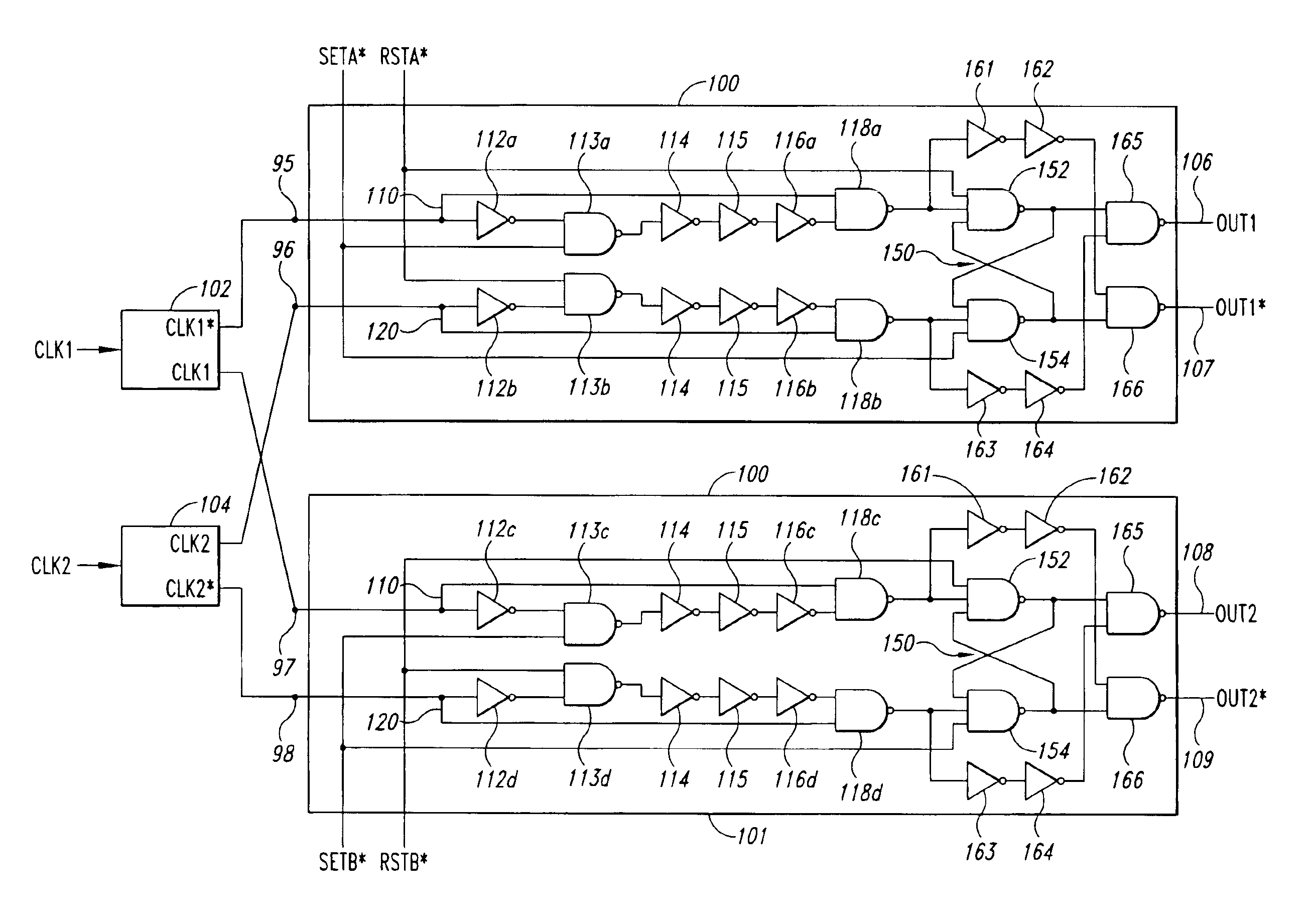
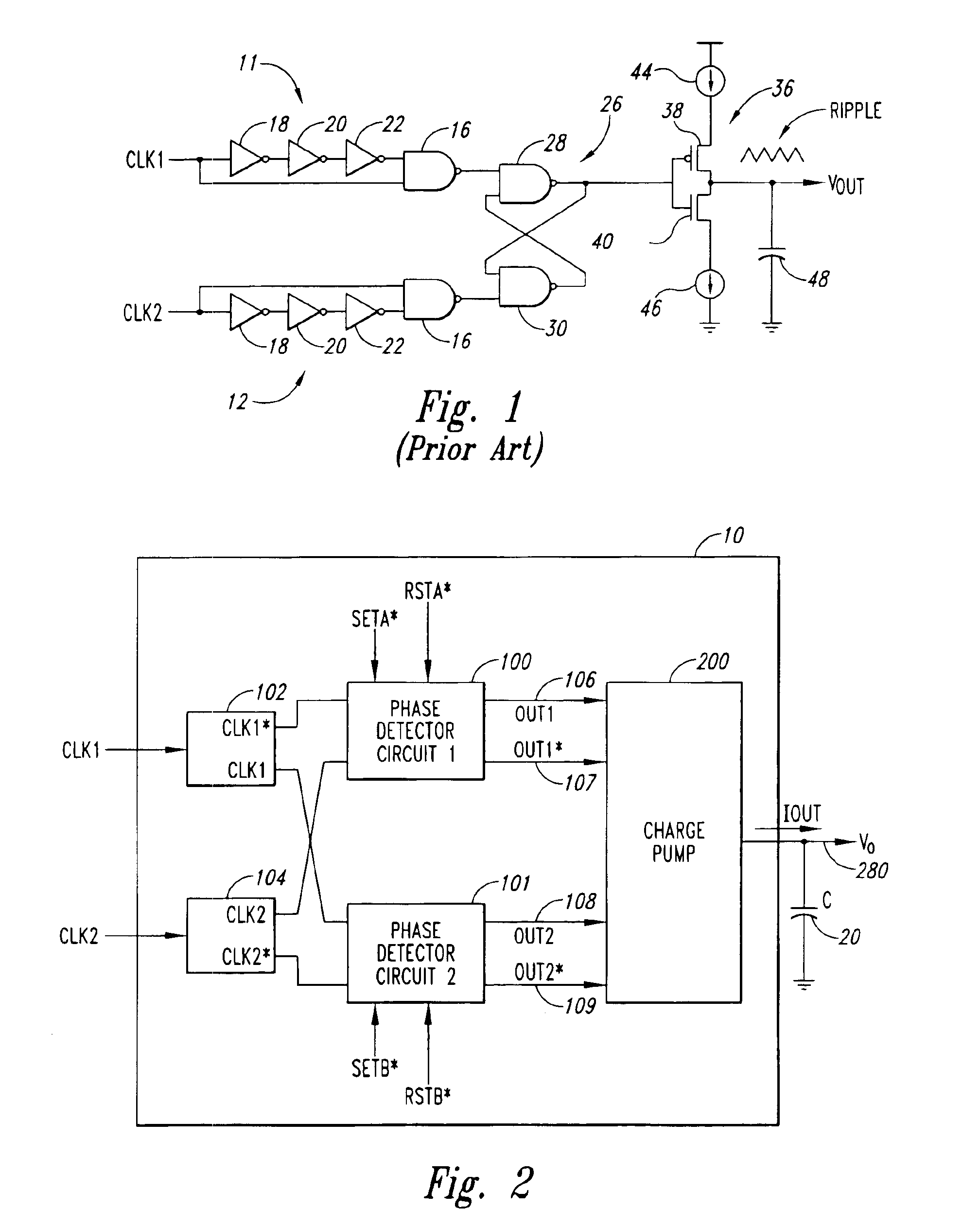
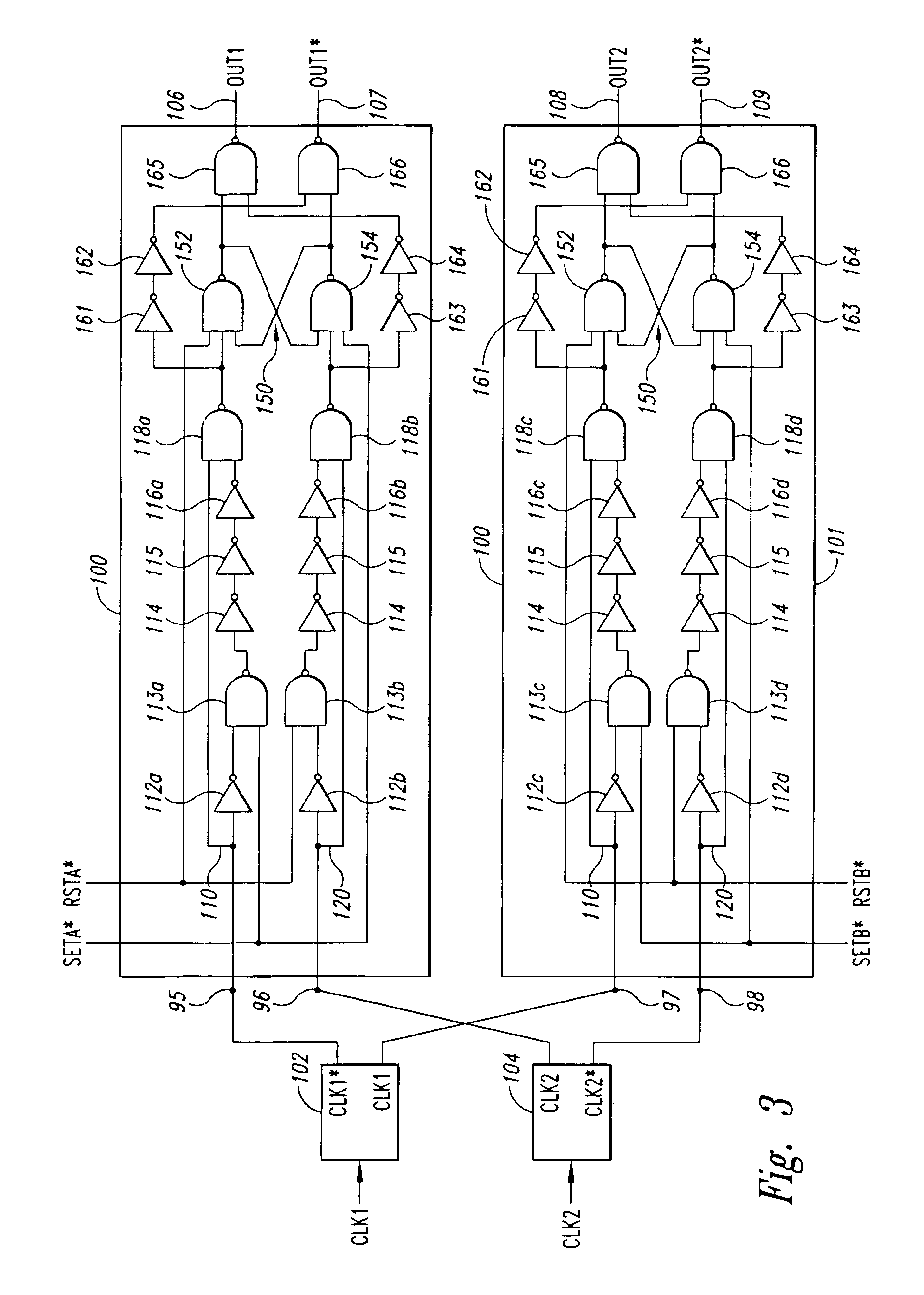
[0023]An embodiment of a phase detector 10 in accordance with the present invention is illustrated in FIG. 2. The phase detector includes two single-to-dual signal converters 102, 104 that receive input clock signals CLK1, CLK2, respectively, and produce complementary clock signals CLK1*, CLK2* and non-complementary clock signals CLK1, CLK2 based on the original input clock signals. The single-to-dual signal converters may be implemented using a variety of designs known to one skilled in the art. For example, an inverter and transfer gate having the same propagation delay connected in parallel will produce a complementary and a non-complementary signal from an input clock signal. The CLK1, CLK1*, CLK2, CLK2* signals are transmitted to two phase detector circuits 100, 101 that produce select signals OUT1, OUT1*, OUT2, OUT2* and transmits them to a phase dependent signal source or a charge pump 200 via signal lines 106, 107, 108, 109, respectively. The charge pump 200 in turn generate...


PUM


Abstract

A phase detector generates a phase dependent control signal according to the phase relationship between a first and second clock signal. The phase detector includes first and second phase detector circuits receiving the first and second clock signals and generating select signals having duty cycles corresponding to the phase relationship between the clock edges of the first and second clock signals. The phase detector also includes a charge pump that receives select signals from the phase detector circuits and produces an increasing or decreasing control signal when the first and second clock signals do not have the predetermined phase relationship, and a non-varying control signal when the first and second clock signals do have the predetermined phase relationship. The control signal may be used to adjust the delay value of a voltage-controlled delay circuit in order to adjust the phase relationship between the first and second clock signals to have a predetermined phase relationship.

Description

CROSS-REFERENCE TO RELATED APPLICATION[0001]This application is a divisional of U.S. patent application Ser. No. 09 / 260,212, filed Mar. 1, 1999 now U.S. Pat. No. 6,470,060.TECHNICAL FIELD[0002]This invention relates to generating a control signal and, more particularly, to generating a control signal based on the phase relationship between two input clock signals, and to memory devices and computer systems using such control signal generators.BACKGROUND OF THE INVENTION[0003]Conventional computer systems include a processor (not shown) coupled to a variety of memory devices, including read-only memories (“ROMs”) which traditionally store instructions for the processor, and a system memory to which the processor may write data and from which the processor may read data. The processor may also communicate with an external cache memory, which is generally a static random access memory (“SRAM”). The processor also communicates with input devices, output devices, and data storage devices...

Claims


Application Information

Patent Timeline
Patent Type & Authority Patents(United States)
IPC IPC(8): H03L7/087H03K5/13H03L7/08H03K5/135H03L7/089H03D13/00H03L7/07H03L7/081G11C7/10H03L7/085H04L12/50
CPCG11C7/1072G11C7/222H03D13/004H03K5/131H03K5/135H03L7/07H03L7/0812H03L7/085H03L7/087H03L7/0896H03K5/133H03L7/0816
Inventor HARRISON, RONNIE M.
Owner ROUND ROCK RES LLC
Why Eureka
Try Eureka