Gradient immersion lithography

a technology of lithography and gradient, applied in the field of lithographic apparatus, can solve the problems of increasing the difficulty of na, many fluids are insufficiently transparent, and the index of refraction of fluids may not be sufficient to improve the resolution of images, so as to reduce radiation reflection, increase the angle of incidence of radiation, and increase the resolution of the apparatus

Inactive Publication Date: 2005-10-11
ASML NETHERLANDS BV
View PDF46 Cites 286 Cited by
  • Summary
  • Abstract
  • Description
  • Claims
  • Application Information

AI Technical Summary

Benefits of technology

[0015]It is an aspect of the present invention to provide a lithographic apparatus in which the space between the optical element of the projection system is filled with at least two fluids having different indices of refraction in order to increase the angle of incidence of the radiation on the substrate, thus reducing reflection of the radiation by the wafer and increasing the resolution of the apparatus. As used herein, the term fluid refers to liquids, gases, and / or gels.

Problems solved by technology

Difficulties in optical design make increasing the NA difficult.
One difficulty presented by filling the space between the optical element of the projection system and the substrate with a fluid is the fluid has an index of refraction between the indices of refraction of the optical element and the substrate.
The index of refraction of the fluid may not be sufficient to improve the resolution of the image.
Another problem associated with immersion lithography is that many fluids are insufficiently transparent to 193 nm and 157 nm radiation which would tend to decrease the amount of radiation incident on the substrate.

Method used


Image

  • Gradient immersion lithography
  • Gradient immersion lithography
  • Gradient immersion lithography

Examples


Embodiment Construction

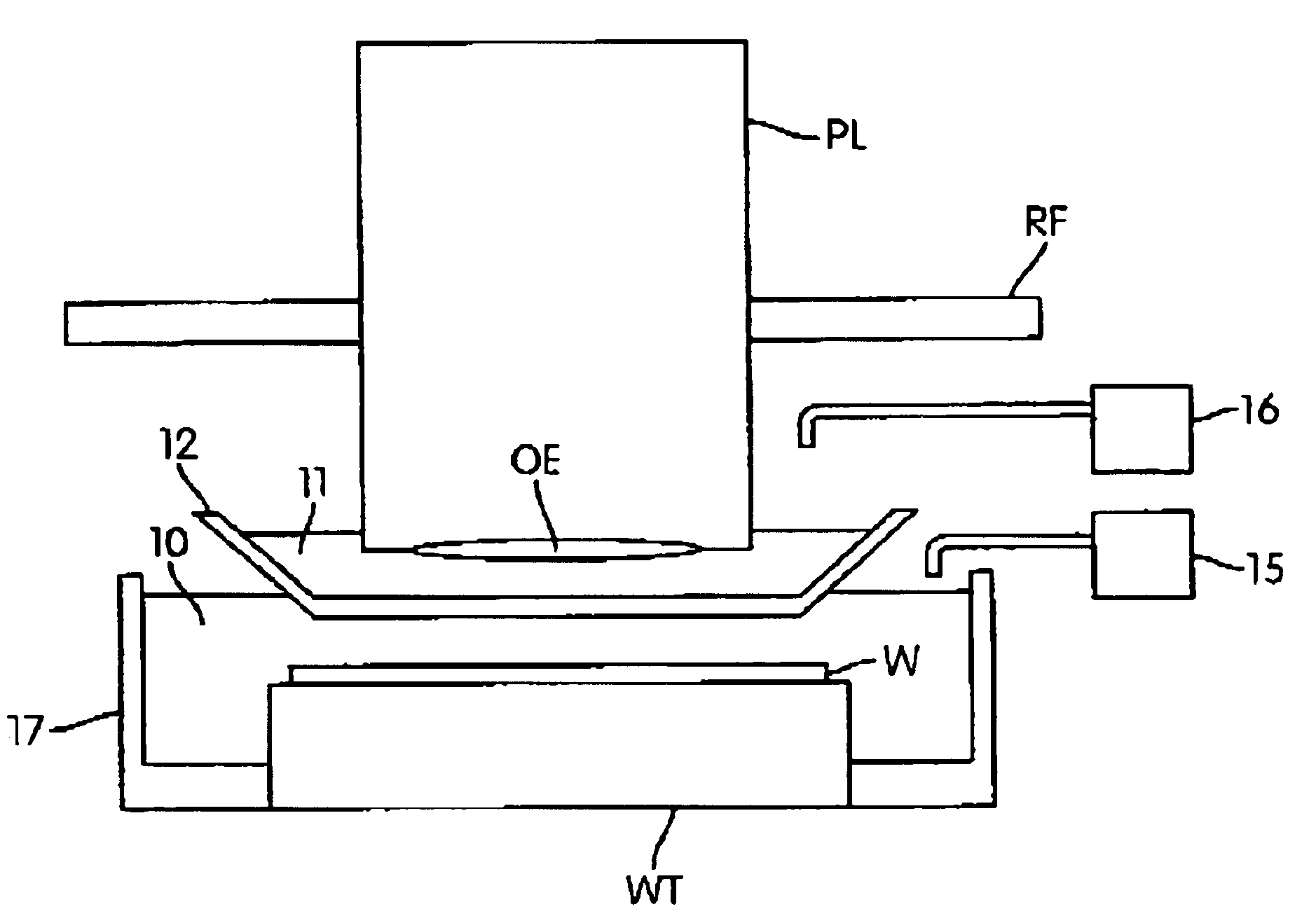
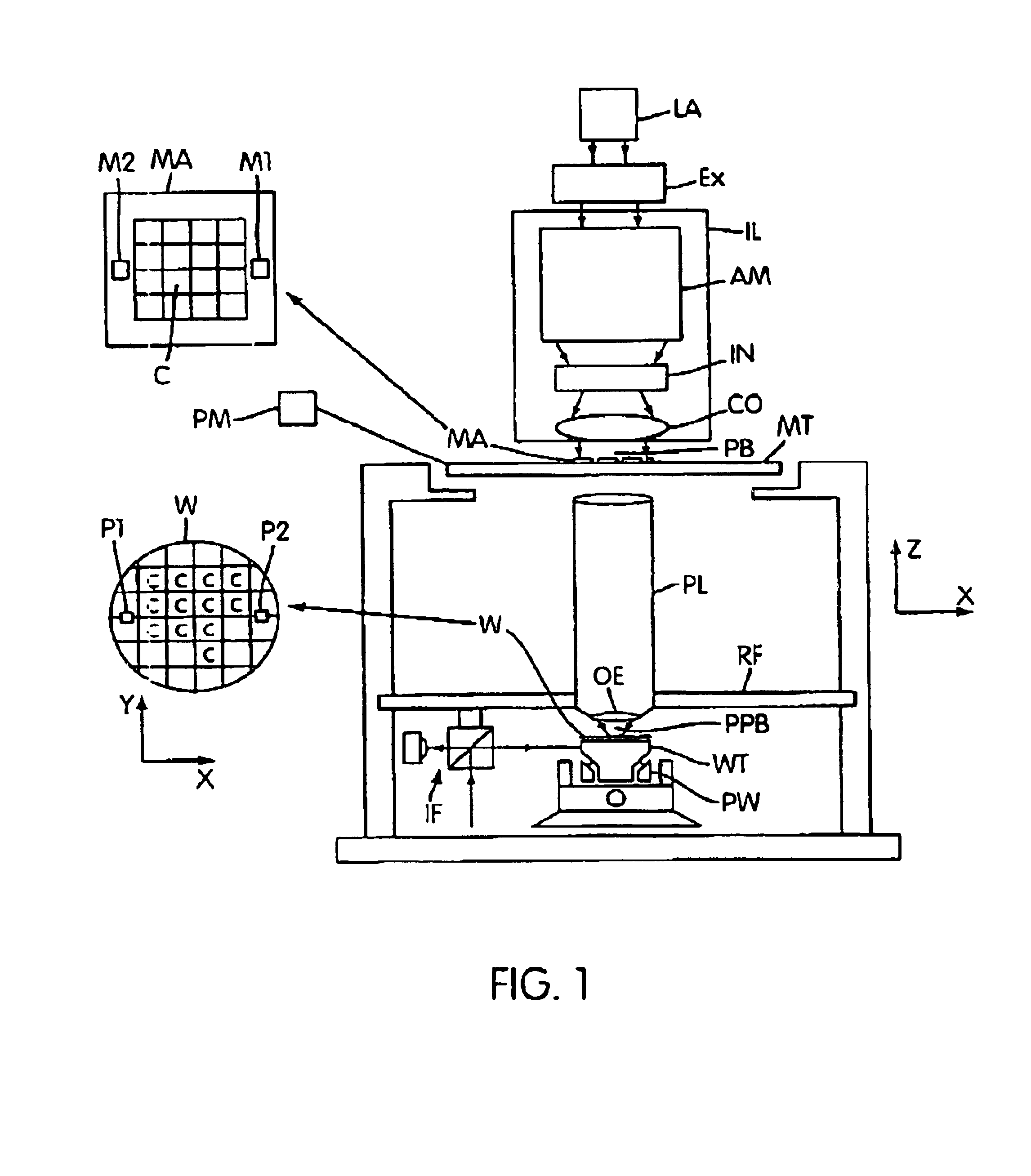
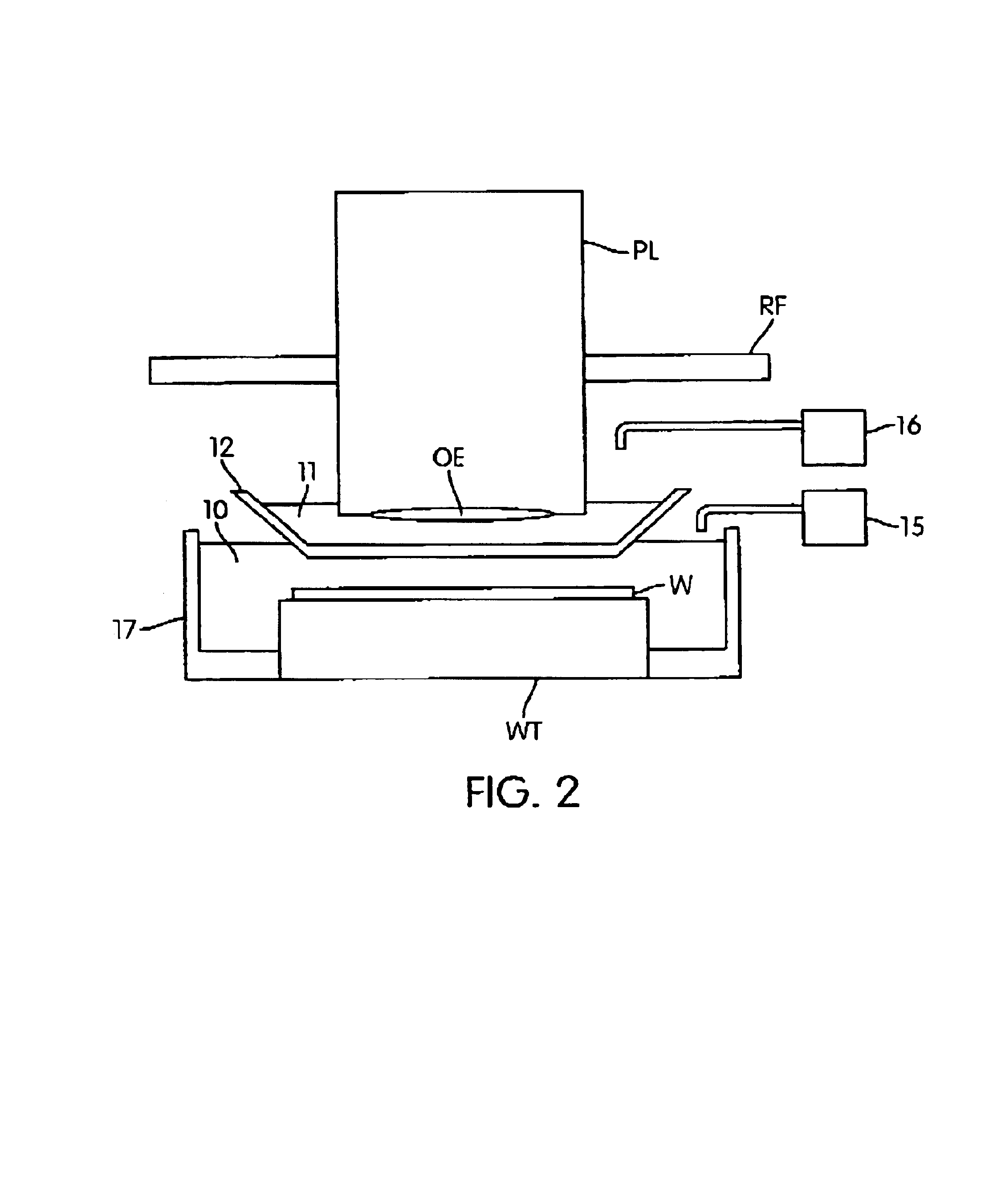
[0028]FIG. 1 schematically depicts a lithographic projection apparatus 1 according to an embodiment of the invention. The apparatus includes a radiation system Ex, IL constructed and arranged to supply a beam PB of radiation (e.g. UV or EUV radiation, such as, for example, generated by an excimer laser operating at a wavelength of 248 nm, 193 nm or 157 nm, or by a laser-fired plasma source operating at 13.6 nm). In this embodiment, the radiation system also comprises a radiation source LA. The apparatus also includes a first object (mask) table MT provided with a mask holder constructed and arranged to hold a mask MA (e.g. a reticle), and connected to a first positioning device PM to accurately position the mask with respect to a projection system or lens PL; a second object (substrate) table WT provided with a substrate holder constructed and arranged to hold a substrate W (e.g. a resist-coated silicon wafer), and connected to a second positioning device PW to accurately position t...


PUM

PropertyMeasurementUnit
widthsaaaaaaaaaa
wavelengthaaaaaaaaaa

Abstract

In a lithographic projection apparatus, a space between an optical element is filled with a first fluid and a second fluid separated by a transparent plate. The first and second fluids have first and second indices of refraction, respectively, that are different from one another. The first fluid is provided between a substrate and the transparent plate and has an index of refraction similar to the index of refraction of the substrate. The second fluid is provided between the transparent plate and the optical element and has an index of refraction similar to the index of refraction of the optical element. The transparent plate has a third index of refraction between the first and second indices of refraction and may be equal to the first index of refraction or the second index of refraction. A device manufacturing method includes filling a space between the optical element and the substrate with at least two fluids having different indices of refraction.

Description

BACKGROUND OF THE INVENTION[0001]1. Field of the Invention[0002]The present invention relates to a lithographic apparatus, in particular to a lithographic apparatus in which the space between an optical element of a projection system and a substrate is filled with at least two fluids having different indices of refraction. The present invention also relates to a device manufacturing method.[0003]2. Description of the Related Art[0004]The term “patterning device” as here employed should be broadly interpreted as referring to device that can be used to endow an incoming radiation beam with a patterned cross-section, corresponding to a pattern that is to be created in a target portion of the substrate. The term “light valve” can also be used in this context. Generally, the pattern will correspond to a particular functional layer in a device being created in the target portion, such as an integrated circuit or other device. An example of such a patterning device is a mask. The concept o...

Claims


Application Information

Patent Timeline
Patent Type & Authority Patents(United States)
IPC IPC(8): G03F7/20G02B1/10H01L21/027
CPCG03F7/70341G03F7/70958G03F7/70966G03F7/70983Y10S430/162
Inventor FLAGELLO, DONISDOERING, JOHN
Owner ASML NETHERLANDS BV
Why Eureka
Try Eureka