Rotary actuating hydraulic tensioner

Inactive Publication Date: 2005-10-18
BORGWARNER INC
View PDF19 Cites 45 Cited by
  • Summary
  • Abstract
  • Description
  • Claims
  • Application Information

AI Technical Summary

Benefits of technology

[0010]The rotary actuating tensioner of the invention provides a hydraulically actuated tensioner of reduced size, but with performance capabilities exceeding torsion spring tensioners. The rotary actuating tensioner of the invention requires less spring force than tra

Problems solved by technology

In systems with large center distances between the sprockets, both strands may evidence slack between the sprockets.
The loss of chain tension can cause undesirable vibration and noise in the chain strands.
The loss of chain tension also increases the possibility of chain slippage or unmeshing from the teeth of the sprocket, reducing engine efficiency and, in some instances, causing system failures.
For example, it is especially important to prevent the chain from slipping in the case of a chain-driven camshaft in an internal combustion engine because misalignment of camshaft timing by several degrees can render the engine inoperative or cause damage to the engine.
Moreover, wear to the chain components during prolonged use also may produce a decrease in the chain tension.
In addition, the intermittent stress placed on the chain devices in automotive applications due to variation in engine speed, engine load and other stress inducing occurrences can cause temporary and permanent chain tension.
However, they often require an e

Method used


Image

  • Rotary actuating hydraulic tensioner
  • Rotary actuating hydraulic tensioner
  • Rotary actuating hydraulic tensioner

Examples


Embodiment Construction

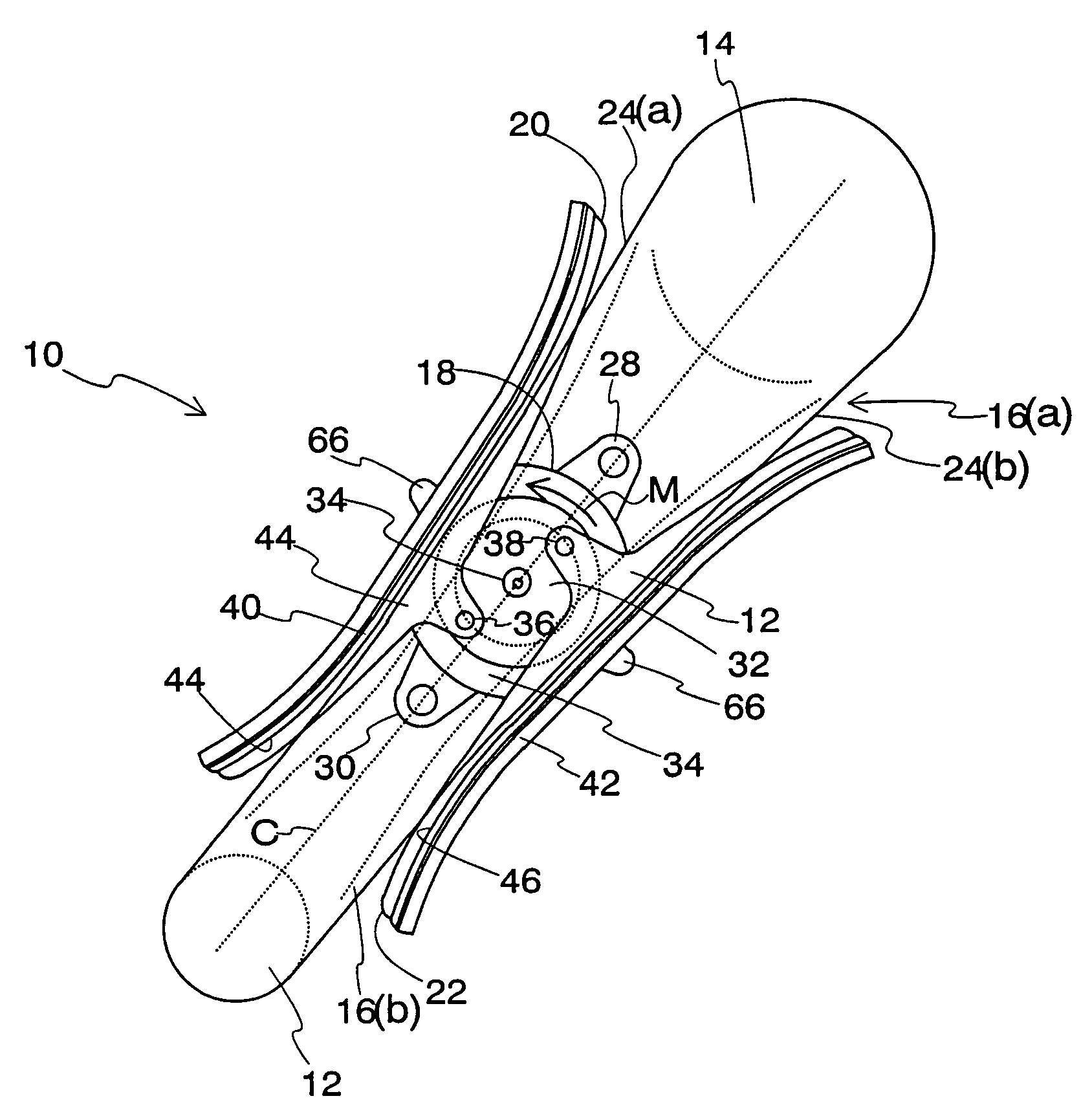
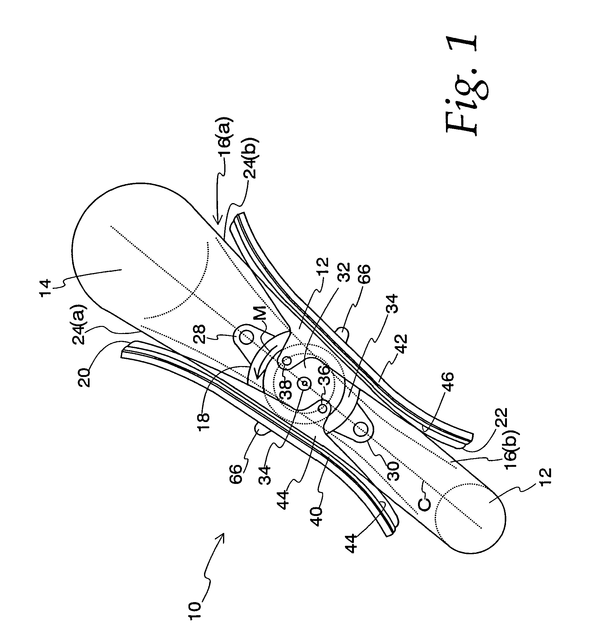
[0046]As shown in FIG. 1, an engine timing system 10 is represented generally by crankshaft sprocket 12 (the drive sprocket) and camshaft sprocket 14 (the driven sprocket). The path of a power transmission chain, i. e., a silent chain, roller chain or the like, is represented by broken chain line 16(a) and the path of the chain where the chain has become elongated as shown by the broken lines 16(b). One aspect of the rotary tensioner system of the present invention is shown with a rotary actuating tensioner 18 and two tensioner arms, 20 and 22.

[0047]In this aspect, the rotary actuating tensioner 18 is located between the strands of the chain 24(a) and 24(b) and between the two sprockets 12 and 14. The rotary actuator 18 is generally centered with respect to the center line C extending between the center of the drive sprocket 12 and the driven sprocket 14. The outer housing of the rotary actuating tensioner 18 possesses two mounting tabs 28 and 30 with mounting bores for attachment o...


PUM


Abstract

An engine tensioning system including tensioner arms and a rotary actuating tensioner capable of driving multiple tensioner arms making multiple chain or belt contacts. The rotary actuating tensioner has connector pins fixed to a rotating surface to which tensioner arms are attached. Rotation of this surface is accomplished through a combination of springs and hydraulic pressure. When the surface rotates, the attached tensioner arms are driven laterally against the engine chain or belt, keeping it taut.

Description

FIELD OF THE INVENTION[0001]The present invention relates generally, but not exclusively, to tensioners used with chain drives in automotive timing and power transmission applications. In particular, the present invention is related to a rotary actuating hydraulic tensioner which combines the benefits of typical hydraulic tensioners and the rotary motion of a torsion spring tensioner.BACKGROUND OF THE INVENTION[0002]Chain tensioning devices are used to control power transmission chains as the chain travels between a set of sprockets. Such chains usually have at least two separate strands, spans or lengths extending between the drive sprocket, such as a crankshaft sprocket, and the driven sprocket, such as a cam sprocket. The strand between the sprockets where the chain leaves the driven sprocket and enters the drive sprocket is frequently under tension as a result of the force imposed on the chain by the drive sprocket. The strand between the sprockets where the chain leaves the dri...

Claims


Application Information

Patent Timeline
IPC IPC(8): F16H7/08F16H7/18F16H7/00
CPCF16H7/0848F16H7/18F16H2007/0806F16H2007/0812F16H2007/0859F16H2007/0874F16H2007/0893
Inventor WIGSTEN, MARK MACDONALDMARKLEY, GEORGE L.
Owner BORGWARNER INC
Why Eureka
Try Eureka