Conversion of petroleum residua to methane

a technology of petroleum residua and conversion method, which is applied in the direction of combustible gas production, combustible gas purification/modification, machines/engines, etc., can solve the problems of high cost of catalyst recovery and recycling, and inability of skilled in the art to practice the conversion of liquid feeds,

Inactive Publication Date: 2005-10-18
PETRO2020
View PDF7 Cites 181 Cited by
  • Summary
  • Abstract
  • Description
  • Claims
  • Application Information

AI Technical Summary

Benefits of technology

[0019]The liquid feed is distributed over a fluidized solid particulate catalyst containing alkali metal and petroleum coke from the lower stage of a two-stage reactor and transported to the upper stage. Particulate solids containing petroleum coke and alkali metal are circulated between the two stages. Superheated steam and recycled hydrogen and carbon monoxide are fed to the lower stage, fluidizing the particulate solids and gasifying some of the carbon in the petroleum coke. The gas phase from the lower stage passes through the upper stage, completing the reaction of the gas phase. The ra...

Problems solved by technology

Currently, petroleum residua are typically subjected to destructive thermal decomposition to yield cracked liquid and gas, and solid petroleum coke.
The '778 and '650 patents disclose that the process chemistry is applicable to carbonaceous feeds in general, but their detailed descriptions teach conversion of coal, and do not enable one skilled in the art to practice the conversion of liquid feeds such as petroleum residua without undue experimentation to determine appropriate means of mixing feed and catalyst, or relative amounts of feed and catalyst.
The recovery and recycle of spent catalyst was therefore expensive and only partially effective.
The rates of feed, steam, and recycle gas were determined by material balance, but this approach is not useful for determining the appropriate contacting of the feed, steam, and recycle gas to a ...

Method used


Image

  • Conversion of petroleum residua to methane
  • Conversion of petroleum residua to methane

Examples


Embodiment Construction

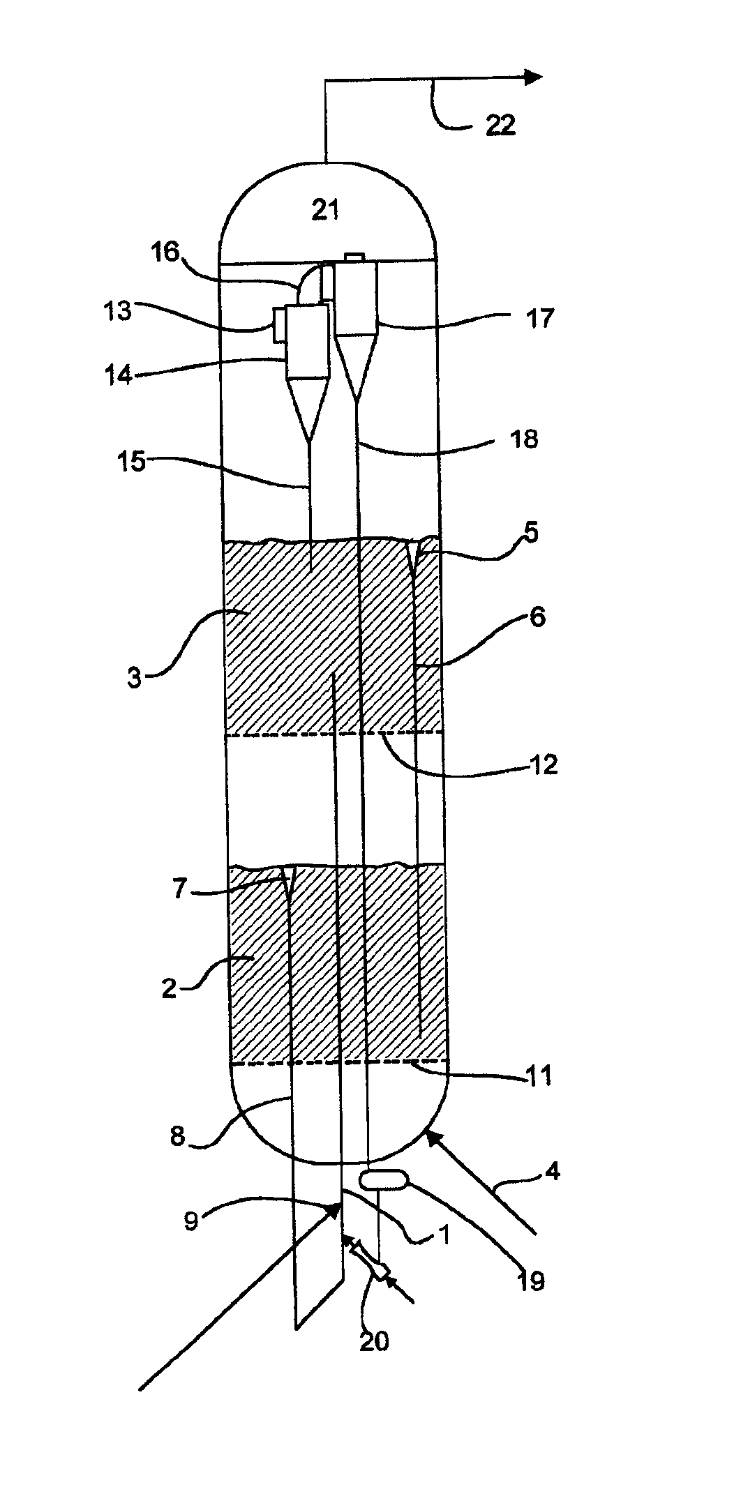
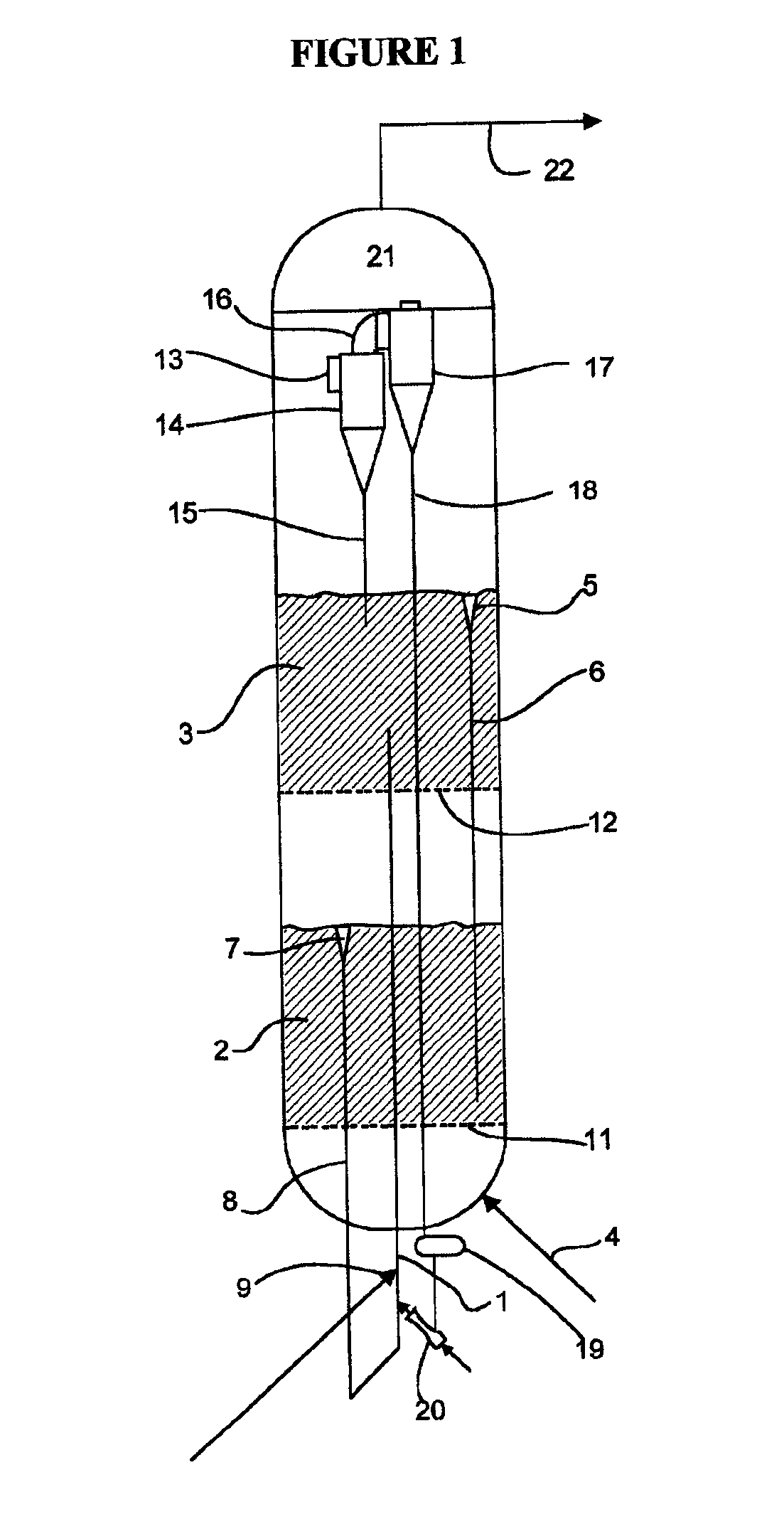
[0021]Petroleum residue or similar carbonaceous liquid feed is preheated to a temperature between 300° F. and 800° F. The feed is atomized and injected through one or more injectors into a gasification reactor system so as to distribute the feed over fluidized particulate solids which are circulated past the feed injectors. The reactor system is maintained at a pressure between 300 psig and 1000 psig, and at a temperature between 1100° F. and 1400° F. The particulate solids are fluidized by a superheated mixture of steam and recycled hydrogen and carbon monoxide. Upon contacting the hot solids, the liquid feed is thermally decomposed, primarily into methane, hydrogen, and solid petroleum coke. The petroleum coke consists primarily of amorphous carbon and high molecular weight condensed ring hydrocarbons, such that the overall hydrogen content of the coke is typically 2% to 4% by mass. Part of the steam reacts with the hydrocarbon portion of the feed to yield methane and carbon dioxi...


PUM

PropertyMeasurementUnit
Temperatureaaaaaaaaaa

Abstract

This invention discloses improvements on previous inventions for catalytic conversion of coal and steam to methane. The disclosed improvements permit conversion of petroleum residua or heavy crude petroleum to methane and carbon dioxide such that nearly all of the heating value of the converted hydrocarbons is recovered as heating value of the product methane. The liquid feed is distributed over a fluidized solid particulate catalyst containing alkali metal and carbon as petroleum coke at elevated temperature and pressure from the lower stage and transported to the upper stage of a two-stage reactor. Particulate solids containing carbon and alkali metal are circulated between the two stages. Superheated steam and recycled hydrogen and carbon monoxide are fed to the lower stage, fluidizing the particulate solids and gasifying some of the carbon. The gas phase from the lower stage passes through the upper stage, completing the reaction of the gas phase.

Description

BACKGROUND OF THE INVENTION[0001]The first step in the refining of crude petroleum (crude oil) is normally distillation to separate the complex mixture of hydrocarbons into fractions of differing volatility. Distillation requires heating to vaporize as much of the liquid as possible without exceeding an actual temperature of about 650° F., since higher temperatures lead to thermal decomposition. The fraction which is not distillable at 650° F. and atmospheric pressure is commonly further distilled under vacuum, such that an actual temperature of 650° F. can vaporize even more liquid, equivalent to a theoretical equivalent of 1050° F. at atmospheric pressure. The remaining undistillable liquid is referred to as petroleum residue, distillation residue, or simply “1050+resid.” This fraction is of low value as a fuel because of its high viscosity and low volatility. Sulfur is concentrated in the residua typically to about 2.5 times the concentration of sulfur in the crude oil. Currently...

Claims


Application Information

Patent Timeline
IPC IPC(8): C10G9/00C10G9/32
CPCC10G9/32C10G2400/26
Inventor NAHAS, NICHOLAS CHARLES
Owner PETRO2020
Why Eureka
Try Eureka