
Biphenyl derivatives and organic electroluminescent device employing the same

a technology of biphenyl derivatives and organic electroluminescent devices, which is applied in the direction of discharge tube luminescnet screens, natural mineral layered products, etc., can solve the problems of shortened lifetime characteristics, difficult suitability of low molecular weight organic el devices, and low emission efficiency of polymer-based el devices, etc., to achieve improved thermal stability and crystal stability, easy purification, and easy formation of thin layers

Active Publication Date: 2005-10-18
SAMSUNG DISPLAY CO LTD
View PDF4 Cites 30 Cited by
  • Summary
  • Abstract
  • Description
  • Claims
  • Application Information

AI Technical Summary

Benefits of technology

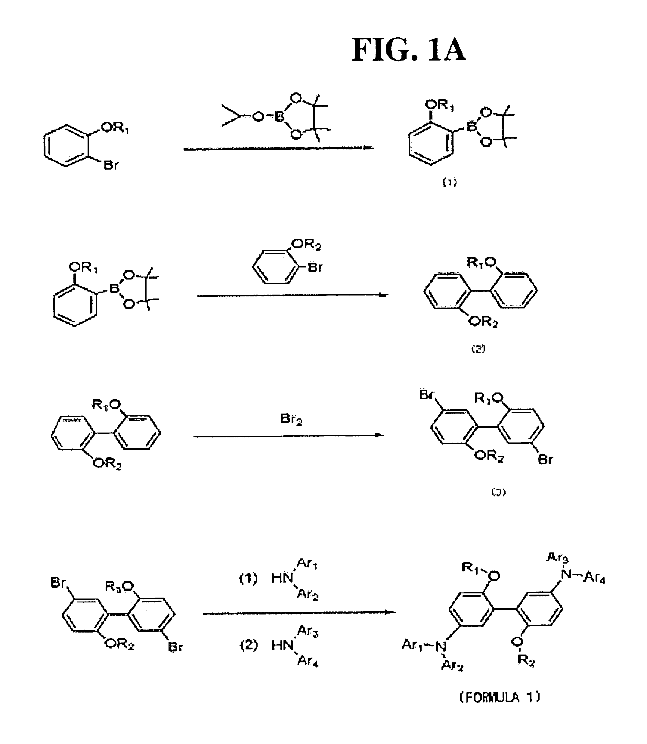
[0014]Various embodiments of the present invention provide biphenyl derivatives, substantially free of molecular defects, having improved thermal stability and crystal stability, that are easily purified, and easily capable of forming a thin layer using a soluble solvent. Embodiments of the present invention also provide an organic EL device with improved emission and efficiency characteristics by employing the biphenyl derivatives.

Problems solved by technology

However, since organic layers typically are formed by vacuum deposition, low molecular weight organic EL devices are difficult to be suitably applied for formation of large-area layers, in which spin coating or ink-jet printing is generally employed.
However, such polymer-based EL devices have lower emission efficiency than low molecular weight EL devices, and they have experienced shortened lifetime characteristics due to deterioration of emissive polymer.
Since defects that promote deterioration in molecular chains are generated during synthesis of such polymer materials and impurities are difficult to refine, it is difficult to obtain high-purity materials.
As far as phosphorescence from a singlet excited state is utilized, a reduction in the external quantum efficiency unavoidably occurs when the injected holes and electrons recombine in the emissive layer.
However, a transition from a triplet excited state to a singlet ground state is forbidden; it is generally a non-radiative transition and there are some difficulties in utilizing the same.
However, after performing vacuum deposition, the emissive layer may gradually lose homogeneity due to crystallization or coagulation, resulting in deterioration in emission efficiency and lifetime characteristics.

Method used


Image

  • Biphenyl derivatives and organic electroluminescent device employing the same
  • Biphenyl derivatives and organic electroluminescent device employing the same
  • Biphenyl derivatives and organic electroluminescent device employing the same

Examples


preparation example 1

Compound Represented by Formula 1a

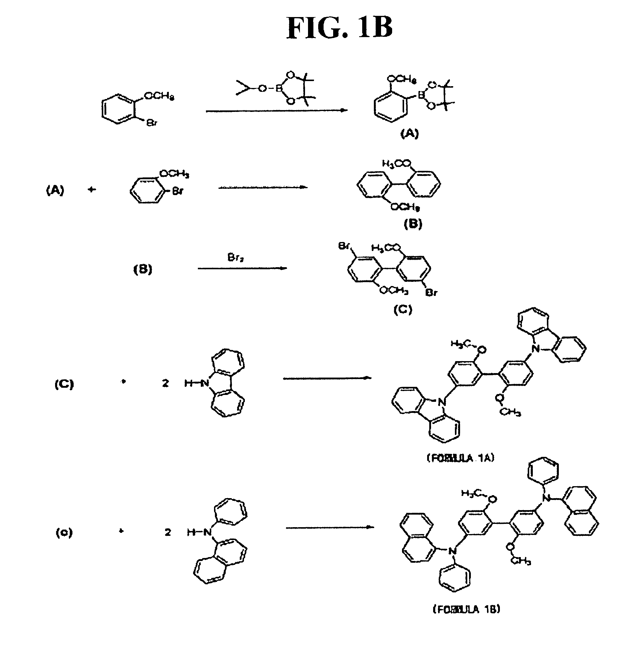
[0088]1. Preparation of Compound (A)

[0089]2-bromoanisole (40 g (214 mmol)) was dissolved in 246 mL of anhydrous THF and cooled to −75° C., and 103 mL (1.2 eq) of n-butyl lithium was slowly added thereto, followed by agitating for about 1 hour. To this was added 51.8 g (1.3 eq) of 2-isopropoxy-4,4,5,5-tetramethyl-1,3,2-dioxaborolane and reacted for 1 hour.

[0090]After the reaction was completed, the reaction mixture was extracted three times using water and ethyl acetate, dried using MgSO4, and concentrated. The concentrated product was subjected to distillation under reduced pressure to remove unreacted 2-isopropoxy-4,4,5,5-tetramethyl-1,3,2-dioxaborolane to produce the compound (A). The structure of the compound (A) was identified through 1H-NMR.

[0091]2. Preparation of Compound (B)

[0092]Compound (A) (10.3 g (44 mmol)) and 7.5 g (1.1 eq) of 2-bromoanisole were dissolved in 29 mL of anhydrous toluene, 29 mL of THF, and 89 mL of 2M Na2CO3 aqueous solut...

preparation example 2

Compound Represented by Formula 1b

[0100]Compound (C) (3 g (8.1 mmol)) and 3.57 g (2.02 eq) of N-phenyl-1-naphthylamine were dissolved in 70 mL of anhydrous toluene, and 2.35 g (3 eq) of sodium tert-butoxide (NaOtBu), 0.08 g (0.05 eq) of tri(tert-butyl)phosphine ((t-Bu)3P) and 0.3 g (0.04 eq) of Pd2(dba)3 as a catalyst were added, and reacted at approximately 120° C. for approximately 48 hours.

[0101]After the reaction was completed, the reaction product was extracted using water and ethyl acetate, and dried, followed by removing side reaction products through open column chromatography using n-hexane as a development solution, thereby producing the compound represented by formula 1b. The structure of the compound represented by formula 1b was identified through 1H-NMR, as shown in FIG. 3. 1H-NMR (CDCl3, δ) 3.59 (s, 6H, 2-OCH3), 6.68-8.03 (m, 3OH, Aromatic Protons).

[0102]FIG. 4A schematically shows preparation processes of compounds represented by formulas 1c and 1d, which will now be...

preparation example 3

Compound Represented by Formula 1c

[0103]1. Preparation of Compound (D)

[0104]2-bromophenol (50 g (290 mmol)) was dissolved in 500 mL of acetone and 48.4 g (350 mmol) of K2CO3 was added thereto. To the reaction product was added 73.3 g (380 mmol) of 1-bromooctane and refluxed for 24 hours.

[0105]After the reaction was completed, the reaction mixture was extracted three times using water and CHCl3, followed by removing K2CO3. Then, organic layers were dried using MgSO4, concentrated, and subjected to column chromatography using n-hexane as a development solution. Unreacted 1-bromooctane was removed from the residue by distillation under reduced pressure, to produce the compound (D). The structure of the compound (D) was identified through 1H-NMR.

[0106]2. Preparation of Compound (E)

[0107]Compound (D) (38 g (130 mmol)) was dissolved in 150 mL of anhydrous THF and cooled to −75° C. and 100 mL (1.2 eq) of n-butyl lithium was slowly added thereto, followed by agitating for about 1 hour. To t...


PUM

PropertyMeasurementUnit
internal quantum efficiencyaaaaaaaaaa
temperatureaaaaaaaaaa

Abstract

A biphenyl derivative having an amino group with or without alkoxy substituent in the biphenyl backbone, and an organic electroluminescent device using the same.

Description

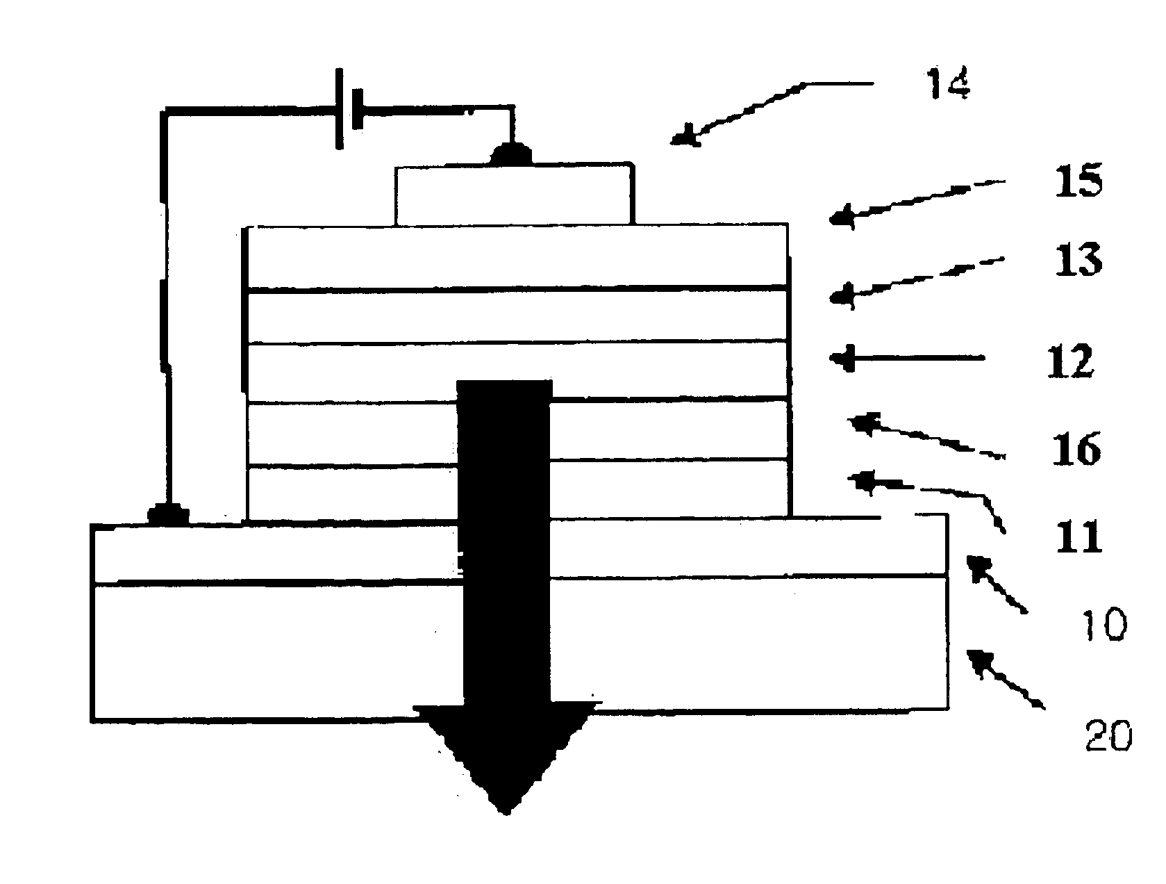
BACKGROUND OF THE INVENTION[0001]1. Field of the Invention[0002]Embodiments of the present invention relate to biphenyl derivatives and an organic electroluminescent device using the same. More particularly, various embodiments of the invention pertain to biphenyl derivatives having alkoxy group(s) and substituted or unsubstituted amino group(s), and an organic electroluminescent device using the same. The electroluminescent device offers improved efficiency and emissive characteristics.[0003]2. Description of the Related Art[0004]An organic electroluminescent (EL) device is an active drive type emission display device that operates under the principle that when current is applied to fluorescent or phosphorescent organic compound layers (hereinafter “organic layers”), electrons and holes are combined in the organic layers to then electroluminesce. Organic electroluminescent devices have various advantages including being lightweight, simple components, having a simplified fabricatio...

Claims


Application Information

Patent Timeline
Patent Type & Authority Patents(United States)
IPC IPC(8): C07C217/00C07C217/92C09K11/06H01L51/05H01L51/30C07D209/82H05B33/14H10K99/00
CPCC07C217/92C09K11/06H01L51/006H01L51/0071H05B33/14C09K2211/1007C09K2211/1011C09K2211/1014C09K2211/1029C09K2211/1044C09K2211/1048C09K2211/1059H01L51/0053H01L51/0067H01L51/007H01L51/0081H01L51/5012H01L51/5096Y10S428/917H10K85/621H10K85/6565H10K85/633H10K85/324H10K85/654H10K85/657H10K50/18H10K50/11
Inventor LEE, SOO-HYOUNGLEE, JI-HOONKIM, SANG-YEOLSOHN, BYUNG-HEESON, JHUN-MO
Owner SAMSUNG DISPLAY CO LTD
Learn More