
Apparatus for enhanced plasmapheresis and methods thereof

a plasmapheresis and apparatus technology, applied in the field of medical apparatuses, can solve the problems of inability to fully utilize cells, and inability to achieve the effect of improving the separation of filtra

Inactive Publication Date: 2005-11-01
XEPMED INC (US)
View PDF13 Cites 48 Cited by
  • Summary
  • Abstract
  • Description
  • Claims
  • Application Information

AI Technical Summary

Benefits of technology

[0012]Enhanced continuous plasmapheresis is accomplished by continually feeding a blood supply through a filtration chamber to effect separation of plasma components and cellular components. The blood passes in essentially parallel to the plane of the filtration membrane at flow rates sufficient to create shear stress across the membrane in the order of 10 to 2,000 dynes / cm2, a preferred range being from about 100 to about 1,000 dynes / cm2. The membrane has a pore size, pore shape, and cells affinity sufficient to allow the plasma components to pass therethrough but retain cellular components thereon. Generally pore sizes of from 0.2 to 1.0 microns are preferred for plasma or platelet separation. Transmembrane pressure of from about 10 mmHg to about 1,000 mmHg are employed to separate the blood into cellular components and plasma fractions. With assistance of the orbital motion of the membrane, the local flow rate and shear stress can be controlled, resulting in a narrower range of the transmembrane pressure that has lower hemolysis and lower plugging propensity.

Problems solved by technology

The separation of blood into cellular component fractions and plasma fractions has inherently some difficulties and complications.
If cellular components are not handled correctly, the cells may lose their functionality and become useless.
In any plasmapheresis-type process effected by ultrafiltration there are various problems which occur during the fractionating of the blood by passing it in a parallel flow pattern over a membrane surface, with a transmembrane pressure sufficient to push the plasma portion of the blood therethrough, while allowing the cellular component portion of the blood to remain thereon.
One of these problems is that the flow rates must be controlled fairly closely.
Thus, if the flow rate employed is too fast at any moment or at any specific region, detrimental turbulence may occur and excess shear force may cause unwanted hemolysis resulting in general destruction of cellular components.
On the other hand, if the flow rate and the transmembrane pressure are not controlled adequately the cellular and macromolecular components of the blood will tend to clog up the membrane thus significantly slowing the ultrafiltration rate.
Such clogging can also cause hemolysis to occur.
Though the average flow rate of the disclosed device is within the non-hemolysis range, the local flow rate and its shear force at any moment and / or at any specific region of the filter membrane may not be adequate to effect the most efficient plasmapheresis.
However, Solomon et al. device requires enormous membrane surfaces for blood plasma separation which appear not economically practical.
During high centrifugal rotation, a portion of the cellular components may undesirably remain in the rotational device or inside pores of the filter membrane for a prolonged time and may subject to hemolysis, cellular damage or membrane clogging.
The requirement of a proper shear force at the outer-most region in a rotational separator apparently limits the size, and therefore the capacity, of the separation apparatus or the spinner.
The pulsatile flow is known to cause certain degrees of turbulence as the pulsatile flow rate changes constantly which may possibly cause cell damage and membrane clogging.
This additional equipment setup and control mechanism for repetitively reversing the transmembrane pressure difference makes this process less economically attractable.

Method used


Image

  • Apparatus for enhanced plasmapheresis and methods thereof
  • Apparatus for enhanced plasmapheresis and methods thereof
  • Apparatus for enhanced plasmapheresis and methods thereof

Examples


Embodiment Construction

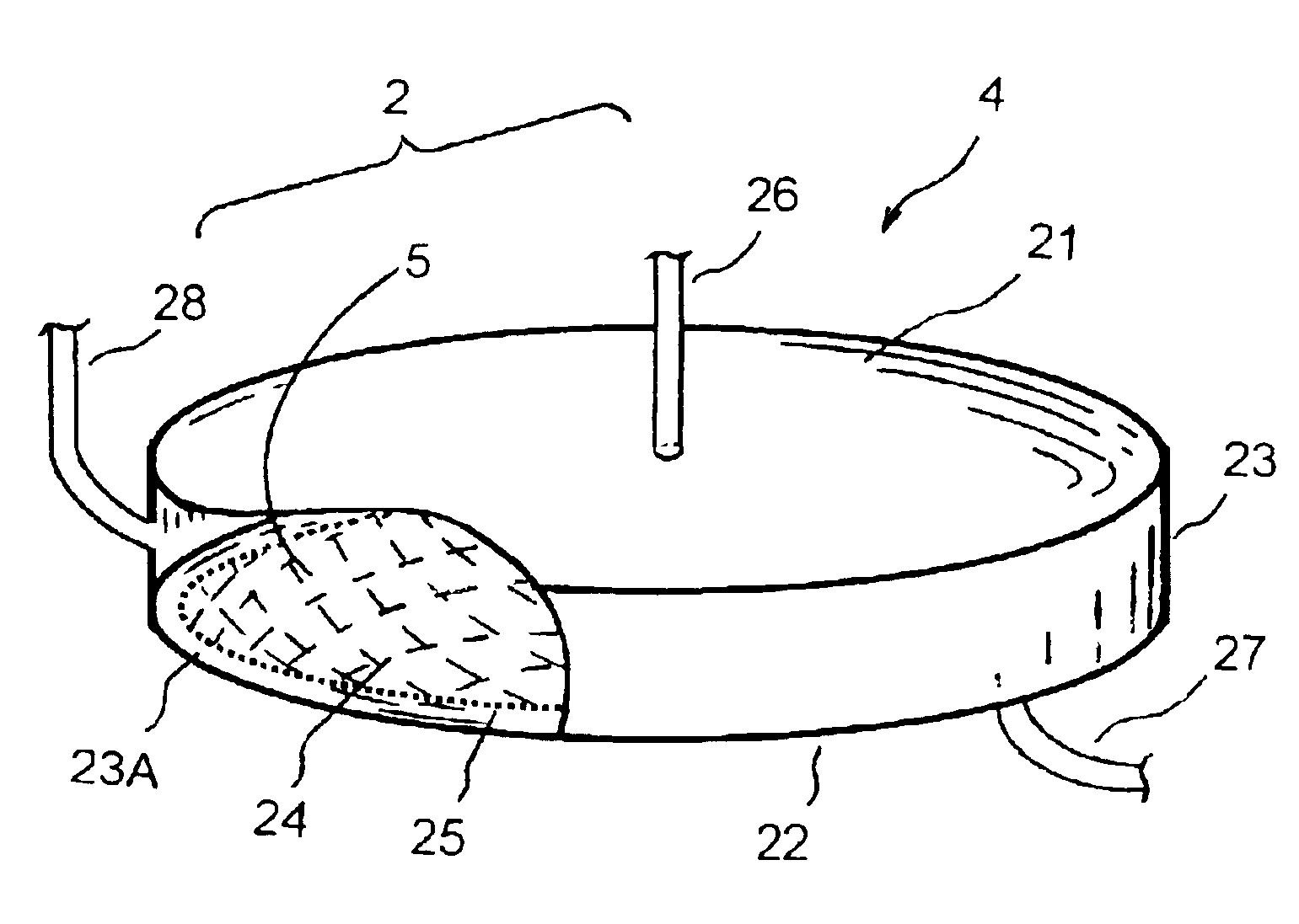
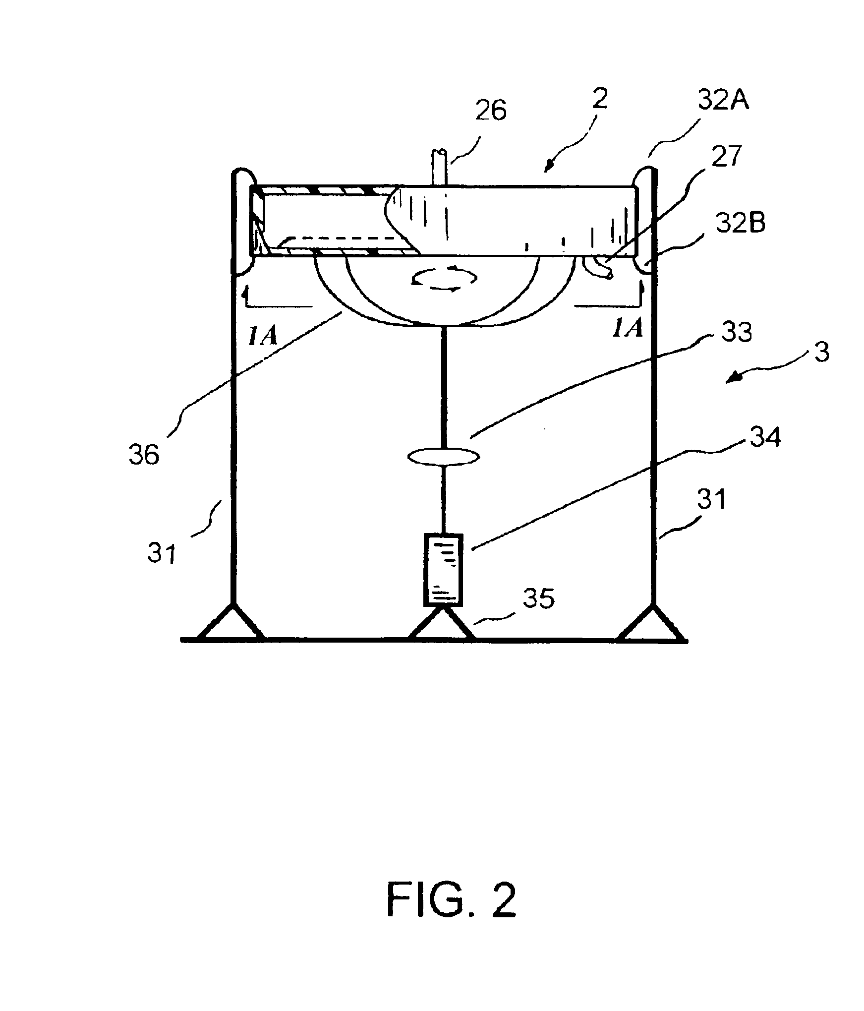
[0023]Referring to FIGS. 1 to 4, what is shown is an embodiment of the enhanced separation process employing a separation chamber comprising a filter membrane under an orbital motion. The enhanced separation process is particularly applicable for plasmapheresis and other medical applications, such as for blood fractionation, for blood autotransfusion, for bone marrow transfusion, for peripheral stem cell transfusion, and the like.

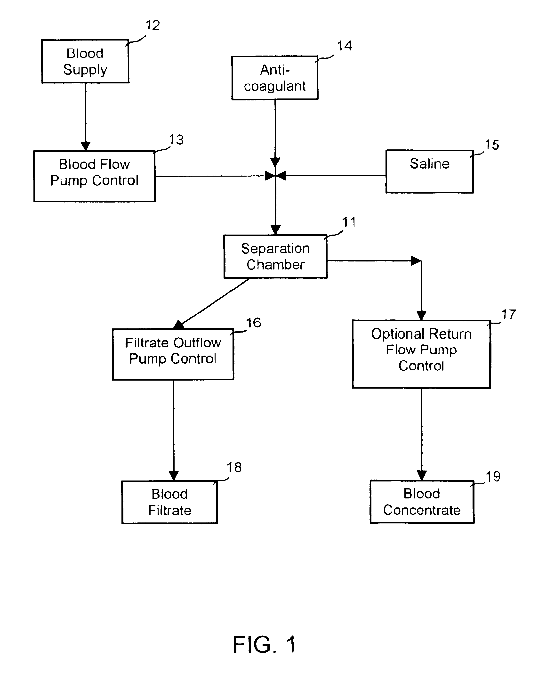
[0024]FIG. 1 shows a schematic diagram of an enhanced blood separation process employing a separation chamber comprising a filter membrane under an orbital motion of the present invention. The blood supply 12 to the apparatus 11 may comprise fresh whole blood, thawed blood, or partially fractionated blood. The blood supply is fed to the separation chamber 11 via a blood flow pump control 13 or other means for directing a blood into the separation chamber 11. To maintain the blood supply from coagulation, anticoagulant 14 may optionally be added into the blo...


PUM

PropertyMeasurementUnit
Densityaaaaaaaaaa
Adsorption entropyaaaaaaaaaa

Abstract

An apparatus and methods for enhanced plasmapheresis comprising a filter membrane under an orbital motion or movement that has optimal local shear forces and maximum plasma flow output. The methods for biological separation and therapies comprise platelet collection, viral particle removal, cell washing and processing for stem cell selection, bone marrow purging, red blood cell collection, auto-transfusion, auto-immune disease treatment, selective macro-molecule removal, toxin removal, LDL removal, extracorporeal plasma delipidation, and the like.

Description

RELATIONSHIP TO COPENDING APPLICATIONS[0001]This patent application is a continuation-in-part of application Ser. No. 09 / 496,613 filed Feb. 2, 2000 now U.S. Pat. No. 6,423,023, entitled “Method and Apparatus for Enhanced Plasmapheresis”, incorporated herein by reference in its entirety.TECHNICAL FIELD OF THE INVENTION[0002]The present invention generally relates to medical apparatus and methods for separating a suspension of plasma alone and / or with platelets from whole blood. More particularly, the invention relates to an apparatus and methods for enhanced plasmapheresis comprising a filter membrane under an orbital motion that has optimal local shear forces and maximum plasma flow output.BACKGROUND OF THE INVENTION[0003]Separation of blood into a plasma fraction and a cellular component fraction is desirable for many medical reasons. For example, separation of blood into plasma fractions and cellular component fractions provides for a collection of plasma alone, with the cellular ...

Claims


Application Information

Patent Timeline
IPC IPC(8): A61M1/34B01D63/16A61M1/16A61M1/26
CPCA61M1/3496B01D63/16A61M1/262A61M1/26A61M1/3693
Inventor CHANG, YU-ANDUFF, DANIELTU, HOSHENG
Owner XEPMED INC (US)
Learn More