Durable electrooptic devices comprising ionic liquids

a technology of electrooptic devices and liquids, applied in the field of electrooptic devices, can solve the problems of limited commercial window applications of these ec devices, high cost and lack of durability, and the durability limitation of ec devices

Inactive Publication Date: 2005-11-01
LOS ALAMOS NATIONAL SECURITY +1
View PDF46 Cites 52 Cited by
  • Summary
  • Abstract
  • Description
  • Claims
  • Application Information

AI Technical Summary

Problems solved by technology

High cost and lack of durability have limited commercial window applications of these EC devices.
The durability limitation of the EC devices arises in part due to the electrolytes and solvents used in the prior art.
in. These papers and patents describe the use of ionic liquids in electrolytes, but fail to give specific details of electrolyte compositions and characteristics of the electrochromic devices made using ionic liqu
A limitation of the use of ionic liquids for electrooptic devices is that many of the known components of electrochromic devices have limited solubility in ionic liquids.
Furthermore, the intrinsic limitations, e.g. electrochemical stability, of known electrochromic dyes and additives, are matched to conventional organic solvents, and therefore these dyes and other additives do not allow the full exploitation of the advantageous properties of the ionic liquids.

Method used


Image

  • Durable electrooptic devices comprising ionic liquids
  • Durable electrooptic devices comprising ionic liquids
  • Durable electrooptic devices comprising ionic liquids

Examples


example 1

[0156]Absorbance spectrum of UV stabilizer in ionic liquid solvent. The absorbance spectra propylene carbonate, 1-Butyl-3-methylimidazolium bis(trifluoromethylsulfonyl)imide (BMI), N-butyl-N-methylpyrrolidinium bis(trifluoromethylsulfonyl)imide (BMP), and a solution of BMI with 1 weight percent of the UV stabilizer ethyl 2-cyano-3,3-diphenyl-acrylate (UVINUL™ 3035, BASF™, Mount Olive, N.J.) were measured between 800 and 250 nm. Both BMI and BMP are ionic liquid solvents used with the invention. BMI has higher absorbance in the UV (below 400nm) than BMP, due to its more conjugated nature. The solution of BMI with 1% UV stabilizer was a clear liquid that did not form a precipitate at −30° C. after 15 hours. The absorbance spectra of the four solutions are shown in FIG. 6.

example 2

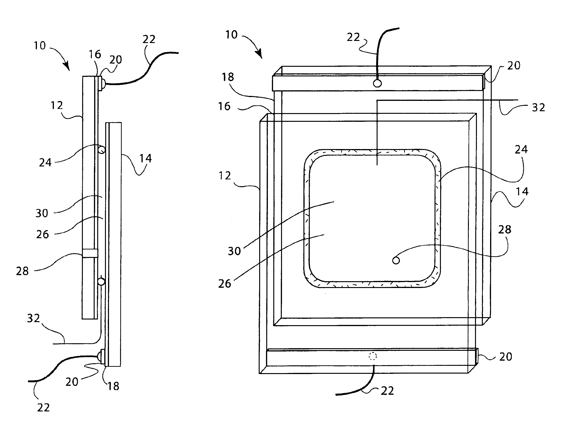
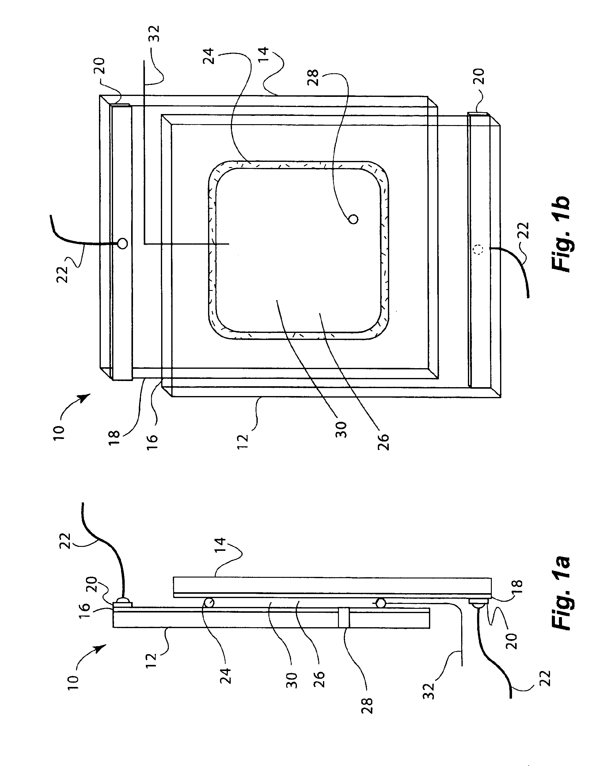
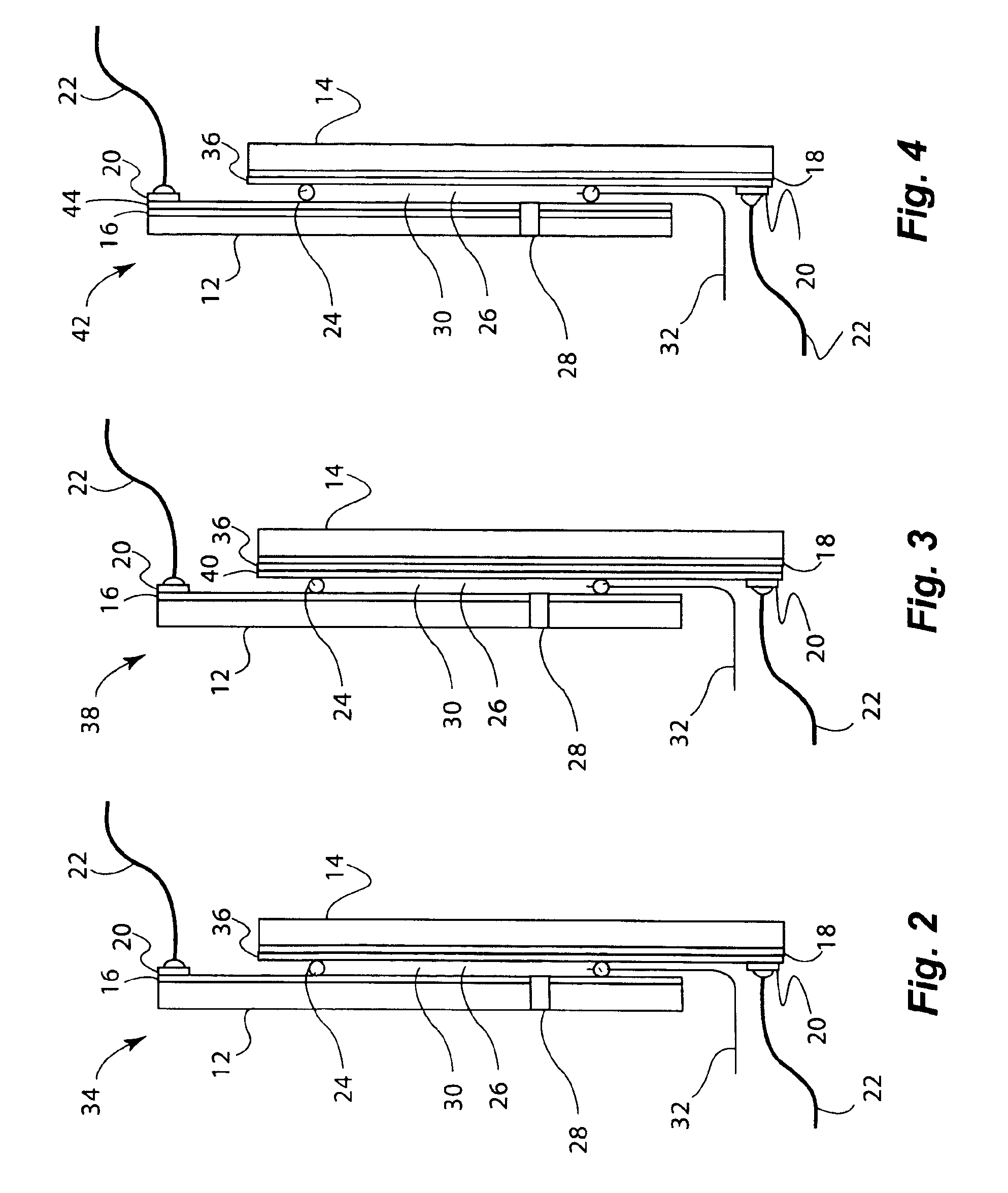
[0157]Electrochromic window device with electrolyte solution including redox dye. ITO substrate (15 Ω / sq) was cut into two 5.25″×3.7″ rectangular pieces. Two holes about 3 mm in diameter were drilled into one piece near the corners one of the diagonals. The substrates were then washed, dried and stored under clean room conditions. An epoxy containing 105 micron glass bead spacers was dispensed around the edges of one of the substrates, and the second substrate was placed on top of it to make a cavity such that the two substrates were slightly off-centered along the long side of the rectangular edge. The perimeter seal width was about 2 mm. This exposed edge on both substrates was later used to apply a busbar and make electrical connections. The epoxy seal was cured at a temperature of 120° C. The cavity was filled at room temperature with a liquid electrolyte solution containing 0.015 M of the charge transfer complex formed by N,N′-dimethylviologen bis(trifluoromethanesulfonyl)imide...

example 3

[0158]Electrochromic window device having a tungsten oxide coating. Two half wave ITO substrates (15 Ω / sq) were prepared as described in EXAMPLE 2 except that the substrate that was not drilled into was coated with a 300 nm thick tungsten oxide coating (on the conductive side) containing 30 mole % of lithium oxide (based on tungsten atoms). This coating was applied by a wet chemical method as described in U.S. Pat. No. 6,266,177, incorporated by reference herein. Any other method such as chemical vapor deposition and physical vapor deposition could have been used to deposit the tungsten oxide layer. The coating was fired at a temperature of 135° C. in a humid atmosphere, and then at 250° C. in air. It was then fabricated into a cell as described in EXAMPLE 1. The cavity thickness was 175 microns. The cavity was filled with electrolyte containing 0.1 molar lithium bis(trifluoromethanesulfonyl)imide, 0.015 M ferrocene, 1 weight percent of ethyl 2-cyano-3,3-diphenyl-acrylate (UVINUL® 3...


PUM

PropertyMeasurementUnit
temperatureaaaaaaaaaa
distanceaaaaaaaaaa
temperaturesaaaaaaaaaa

Abstract

Electrolyte solutions for electrochromic devices such as rear view mirrors and displays with low leakage currents are prepared using inexpensive, low conductivity conductors. Preferred electrolytes include bifunctional redox dyes and molten salt solvents with enhanced stability toward ultraviolet radiation. The solvents include lithium or quaternary ammonium cations, and perfluorinated sulfonylimide anions selected from trifluoromethylsulfonate (CF3SO3−), bis(trifluoromethylsulfonyl)imide ((CF3SO2)2N−), bis(perfluoroethylsulfonyl)imide ((CF3CF2SO2)2N−) and tris(trifluoromethylsulfonyl)methide ((CF3SO2)3C−). Electroluminescent, electrochromic and photoelectrochromic devices with nanostructured electrodes include ionic liquids with bifunctional redox dyes.

Description

RELATED APPLICATIONS[0001]This application is a continuation-in-part of U.S. patent application Ser. No. 10 / 600,807 entitled “Electrolytes for Electrooptic Devices Comprising Ionic Liquids” filed Jun. 20, 2003, now U.S. Pat. No. 6,853,472 incorporated by reference herein, and claims priority of U.S. Provisional Patent Application No. 60 / 390,611 entitled “Electrolytes for Electrooptic Devices Comprising Ionic Liquids” filed Jun. 21, 2002, incorporated by reference herein, and U.S. Provisional Patent Application No. 60 / 502,133 entitled “Durable Electrooptic Devices” filed Sep. 11, 2003, incorporated by reference herein.STATEMENT REGARDING FEDERAL RIGHTS[0002]This invention was made with government support under Contract No. W-7405-ENG-36 awarded by the U.S. Department of Energy. The government has certain rights in the invention.FIELD OF THE INVENTION[0003]The present invention relates generally to electrooptic devices and more particularly to durable electrooptic devices that employ ...

Claims


Application Information

Patent Timeline
Patent Type & Authority Patents(United States)
IPC IPC(8): G02F1/01G02F1/00G02B5/23G02B5/22G02F1/153G02F1/15C25B1/00G02FG02F1/1503G02F1/155
CPCB60R1/088C09K9/02C09K2211/1029G02F1/1521G02F1/157G02F2202/36G02F1/1503
Inventor AGRAWAL, ANOOPCRONIN, JOHN P.TONAZZI, JUAN C. L.WARNER, BENJAMIN P.MCCLESKEY, T. MARKBURRELL, ANTHONY K.
Owner LOS ALAMOS NATIONAL SECURITY
Why Eureka
Try Eureka