
System and method for redundant path connections in digital communications network

a digital communication network and redundant path technology, applied in the field of digital communications network, can solve the problems of little or no standard practice as to how redundancy should be implemented, difficult to arrange redundancy in some systems, and incompatible with the application of redundancy in optical networks, etc., to achieve the effect of creating redundancy in the network, reducing the amount of required space, power and extra equipment, and reducing the amount of required

Active Publication Date: 2005-11-01
MACOM CONNECTIVITY SOLUTIONS LLC
View PDF14 Cites 5 Cited by
  • Summary
  • Abstract
  • Description
  • Claims
  • Application Information

AI Technical Summary

Benefits of technology

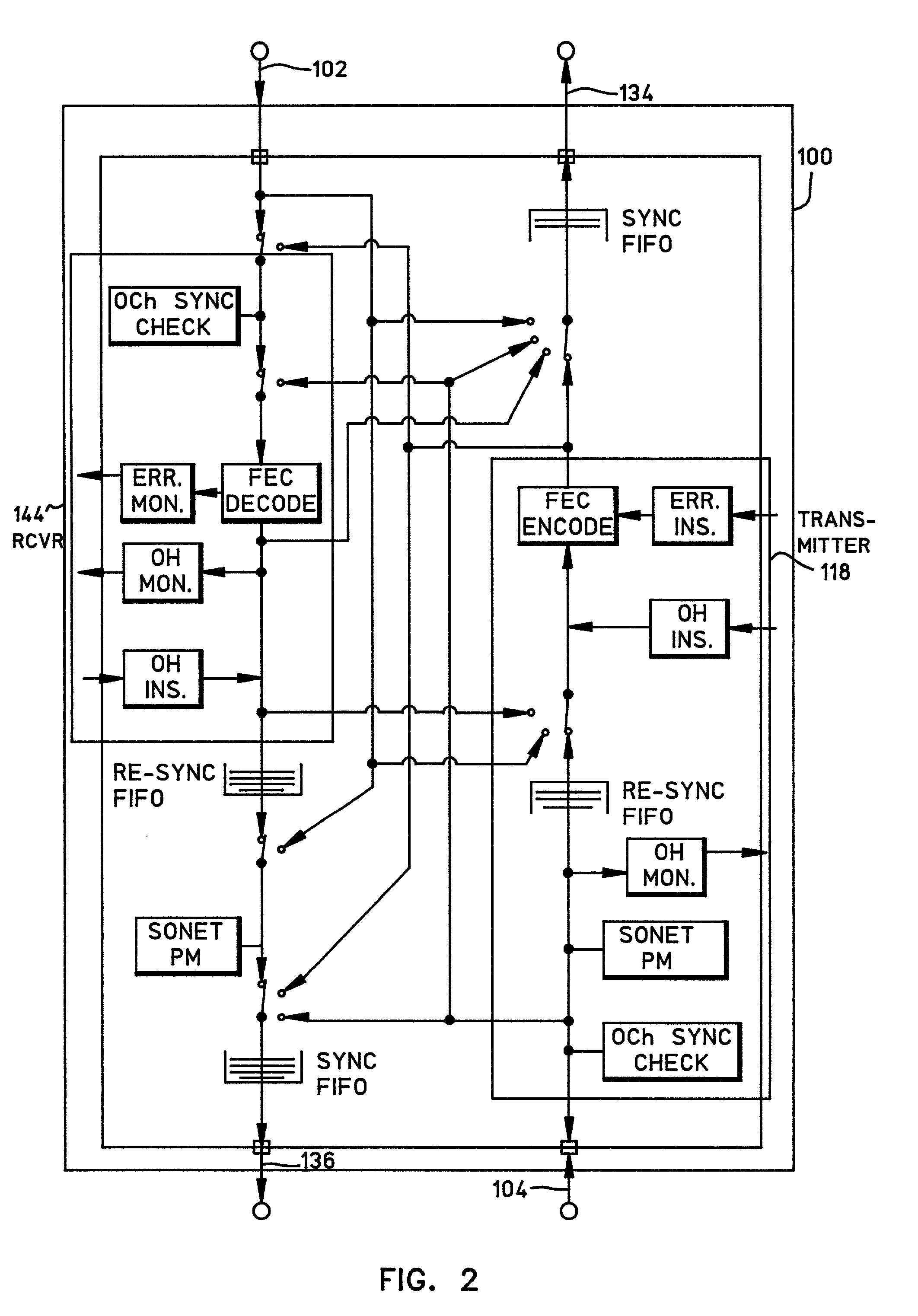
[0011]Accordingly, the invention is an integrated circuit (IC) device which has programmable features to set the active data paths through the device, and to monitor both the selected and non-selected data paths for integrity. The device has two identical inputs and two identical outputs. There are two main blocks within the device, one for encoding and one for decoding. The connection of inputs to the decoder block is programmable, as is the connection of the encoder block to the outputs. The purpose of this invention is to provide 1+1 input and output redundancy in a device targeted at optical networks, so that if an input or output device fails, the network can continue to operate. The invention also integrates diagnostic features and line monitoring support to aid with switching decisions and network troubleshooting. The advantage of this invention is that it provides the user the ability to create redundancy in the network with a minimum of required space, power, and extra equipment. In addition to this, installations are easy to diagnose because of the intergrated loopback functionality. The configurability offered by the invention allows savings in space, required test equipment, and the cost of customer units.

Problems solved by technology

Although an asset in any system, redundancy may be difficult to arrange in some systems due to issues such as cost, throughput efficiency, and space constraints.
All of these constraints work against the application of redundancy in optical networks, such as the synchronous optical network (SONET) for example.
As a result, there is little or no standard practice as to how redundancy should be implemented.

Method used


Image

  • System and method for redundant path connections in digital communications network
  • System and method for redundant path connections in digital communications network
  • System and method for redundant path connections in digital communications network

Examples


Embodiment Construction

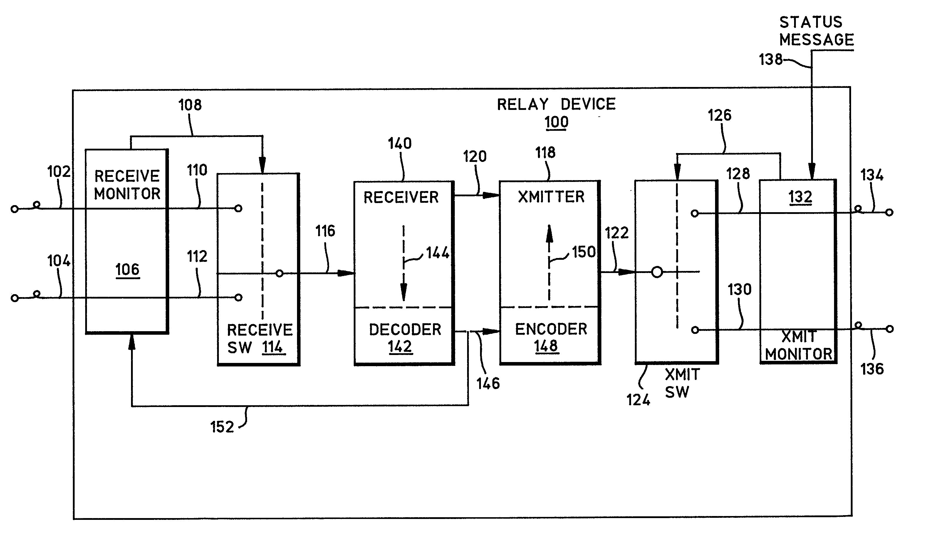
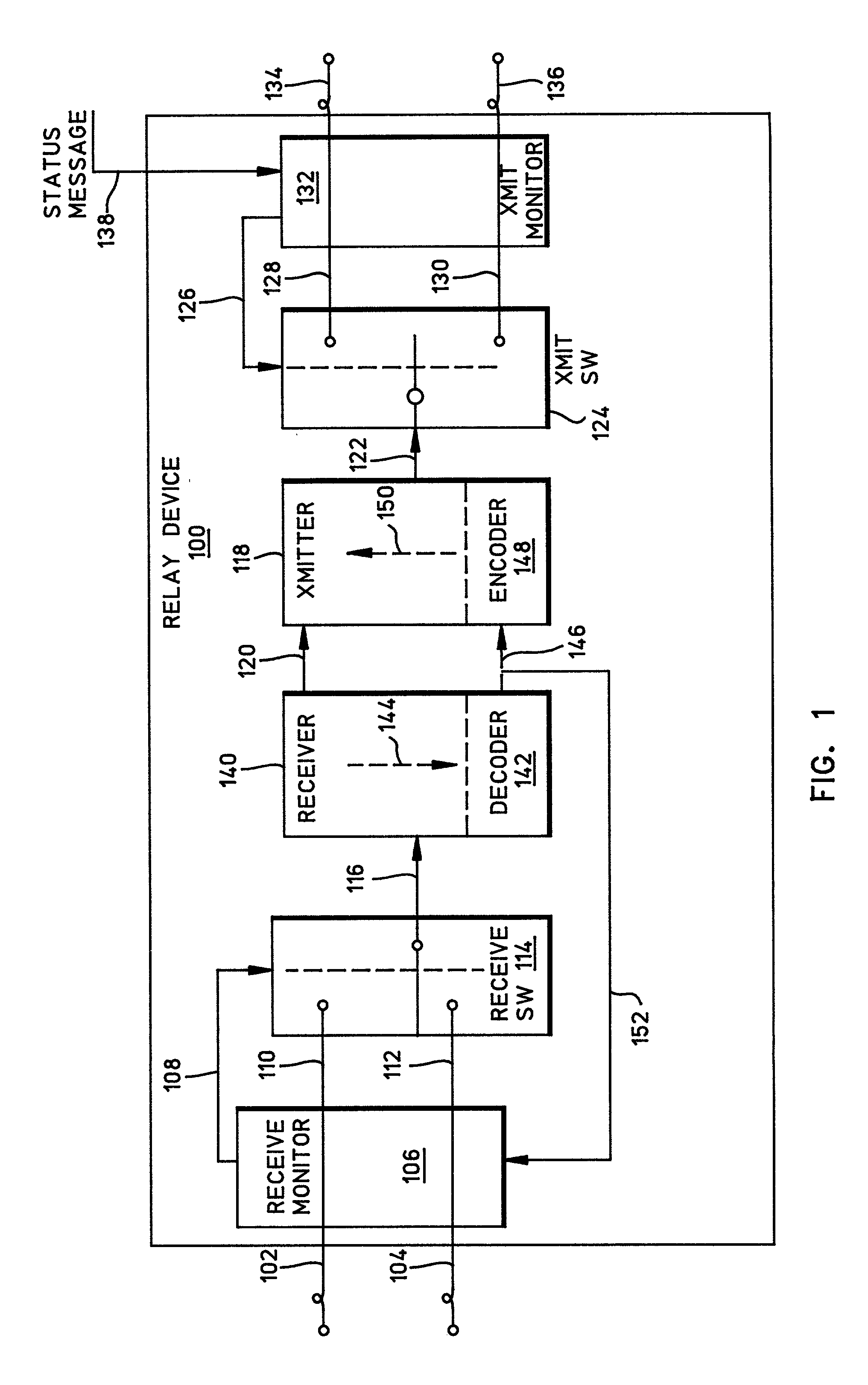
[0020]FIG. 1 is a schematic block diagram of an integrated circuit relay device that provides redundancy. In short, the device 100 has a single line, dual redundant configuration that provides 1+1 redundancy for repeater and transponder applications. Communications on a primary (active), or first receive path 102 are constantly monitored for integrity while in operation. Simultaneously, communications on a secondary (standby), or second receive path 104 are monitored for correct formatting. The results of the monitoring prevent a path switch from occurring, from the first receive path 102 to the second receive path 104, for example, unless the second receive path 104 is healthy.

[0021]The IC digital communication relay device 100 comprises a receive monitor 106 having a first input connected to the first receive path on line 102 and a second input connected to the second receive path on line 104. The receive monitor 106 monitors the integrity of communications on the first and second...


PUM


Abstract

A system and method for providing redundancy in an integrated circuit (IC) relay device has been disclosed. The relay device accepts communications on a first and second receive path. The relay device monitors communications on both the receive paths, and selects a path having a high degree of integrity. Likewise, the relay selectively supplies communications on a first and second transmit path. The relay device selects the transmit path having the proper measure of communication integrity. Communications integrity can be based upon internally monitored criteria such as bit error rate, synchronization, clock signals, and forward error correction. Alternately, the integrity is determined external to the relay, and the relay responds to external switch commands.

Description

RELATED APPLICATIONS[0001]This application contains material related to the following commonly assigned U.S. patent applications incorporated herein by reference:[0002]Ser. No. 09 / 753,184 filed Jan. 2, 2001 for “SYSTEM AND METHOD FOR DIAGNOSTIC MULTICAST SWITCHING”[0003]Ser. No. 09 / 753,183 filed Jan. 2, 2001 for “BIDIRECTIONAL LINE SWITCH RING SYSTEM AND METHOD.”BACKGROUND OF THE INVENTION[0004]1. Field of the Invention[0005]This invention relates generally to a digital communications network and, more particularly, to a system and method for providing redundancy between nodes of the communication network[0006]2. Description of the Related Art[0007]Redundancy is often applied in mission critical networks, or where down time cannot be tolerated. Although an asset in any system, redundancy may be difficult to arrange in some systems due to issues such as cost, throughput efficiency, and space constraints. All of these constraints work against the application of redundancy in optical n...

Claims


Application Information

Patent Timeline
Patent Type & Authority Patents(United States)
IPC IPC(8): H04L25/38H04L25/60
CPCH04L25/0272H04L25/20
Inventor BENDAK, GEORGE BESHARASORGI, ALAN MICHAEL
Owner MACOM CONNECTIVITY SOLUTIONS LLC
Learn More