Steam generator and mixer using the same

a technology of steam generator and mixer, which is applied in the direction of lighting and heating apparatus, heating types, containers, etc., can solve the problems of complex whole apparatus, low thermal efficiency, and inability to quickly heat, and achieve the effect of generating steam in a short period of time, stably and efficiently supplying steam, and convenient construction

Inactive Publication Date: 2005-11-01
COVALENT MATERIALS CORP
View PDF14 Cites 28 Cited by
  • Summary
  • Abstract
  • Description
  • Claims
  • Application Information

AI Technical Summary

Benefits of technology

[0026]The present invention is made in order to solve the above-mentioned technical problems, an aim of the present invention is to provide a steam generator which is capable of supplying steam stably and efficiently, moreover, generating steam in a short period of time, for ease of construction and ease of maintenance.

Problems solved by technology

A disadvantage of such an apparatus is that the steam generating apparatus used for the steam suction apparatus is generally made of metal, such as iron and aluminum and heat from the heater 102 escapes to a body (casing) of the apparatus, so that the water in the heating unit 103 cannot be heated effectively, the thermal efficiency is low, and it is not possible to perform rapid heating.
Thus, there is a problem that the whole apparatus is complicated and its manufacturing costs increase.
Therefore, there is a technical problem that the solid urea should be rapidly heated inside the flue, so that a large-sized heater should be used.
Moreover, the air supply device is used for generating and conveying the above-mentioned thermal decomposition gas (reduction gas), however, there is another technical problem that a temperature in the flue is decreased by the air supply, so that the thermal efficiency is reduced.
Therefore, there is a technical problem that the whole apparatus becomes larger.
Thus, there is another technical problem that the apparatus becomes larger and more complicated so that it is difficult to load it on a vehicle.
In addition, the flue etc. might corrode by ammonia generated when the solid urea is thermally decomposed.
However, there is another technical problem that the application of the coating may be labor intensive and expensive.

Method used


Image

  • Steam generator and mixer using the same
  • Steam generator and mixer using the same
  • Steam generator and mixer using the same

Examples


second embodiment

[0166]Next, the steam generator in accordance with the present invention will be described with reference to FIG. 12. In addition. FIG. 12 show a state where the steam generator is accommodated, together with the thermal insulation material, within the metal casing, FIG. 12A is a cross-sectional view along the line I—I in FIG. 12B, and FIG. 12B is a vertical sectional view.

first embodiment

[0167]This embodiment is such that the steam generator of the above-mentioned first embodiment is surrounded by a thermal insulation material 37.

[0168]In other words, the glass body 10 and the heater unit 20 are surrounded by the thermal insulation material 37, such as glass wool, a fiber flux board, a porous-ceramics block, or rock wool, and further contained in a metal casing 38.

[0169]The glass body 10 and the heater unit 20 are thus surrounded by the thermal insulation material 37, so that it is possible to perform the heating efficiently. Since the steam generator is accommodated in the metal casing 38, it is possible to protect the steam generator against an impact etc. In addition, when the thermal insulation material 37 is glass wool etc., it functions as a so-called shock absorbing material, thus protecting the steam generator against the impact etc.

[0170]Next, a third embodiment of the steam generator in accordance with the present invention will be described with reference...

seventh embodiment

[0186]Next, the steam generator in accordance with the present invention will be described with reference to FIG. 18.

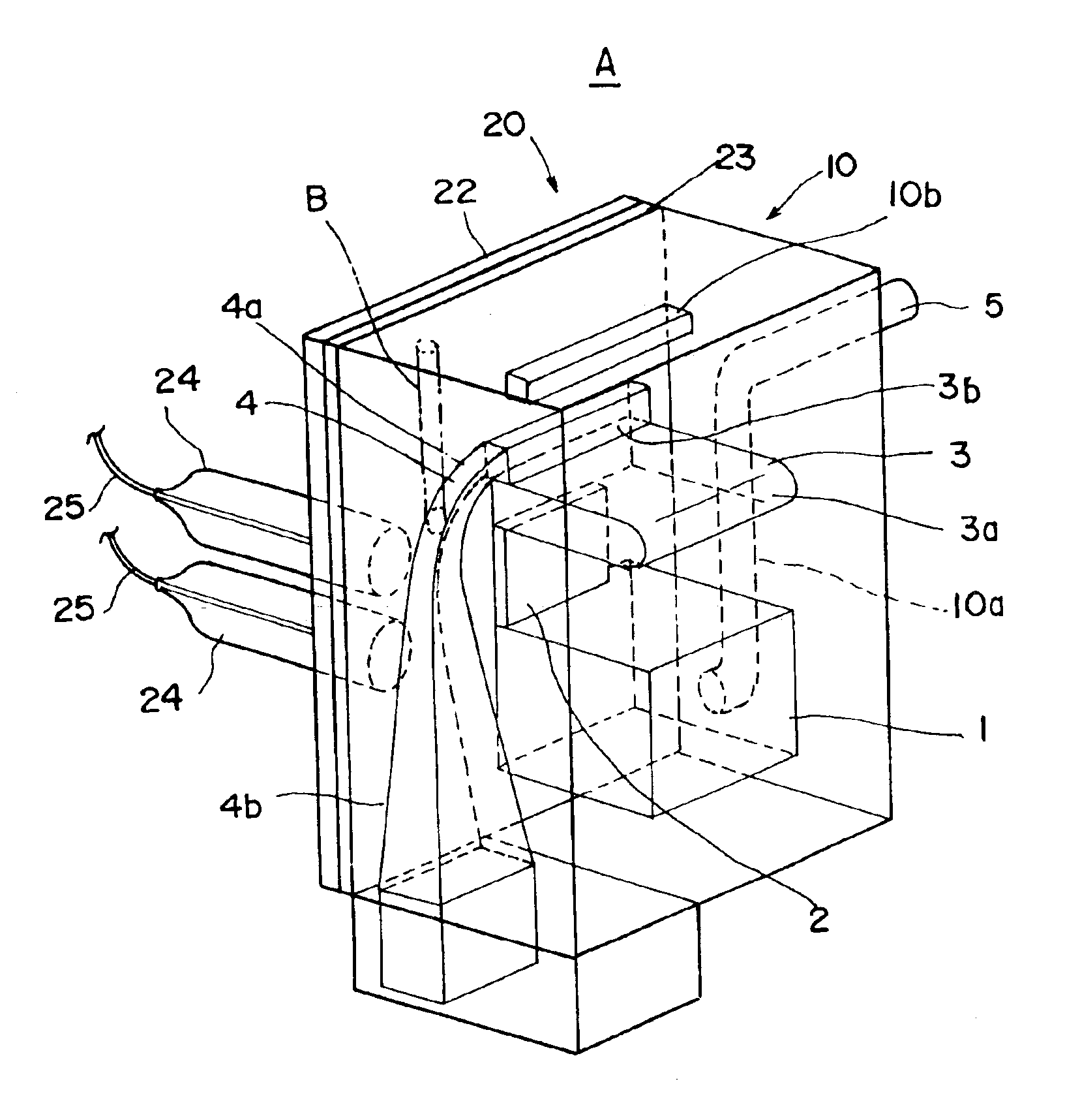
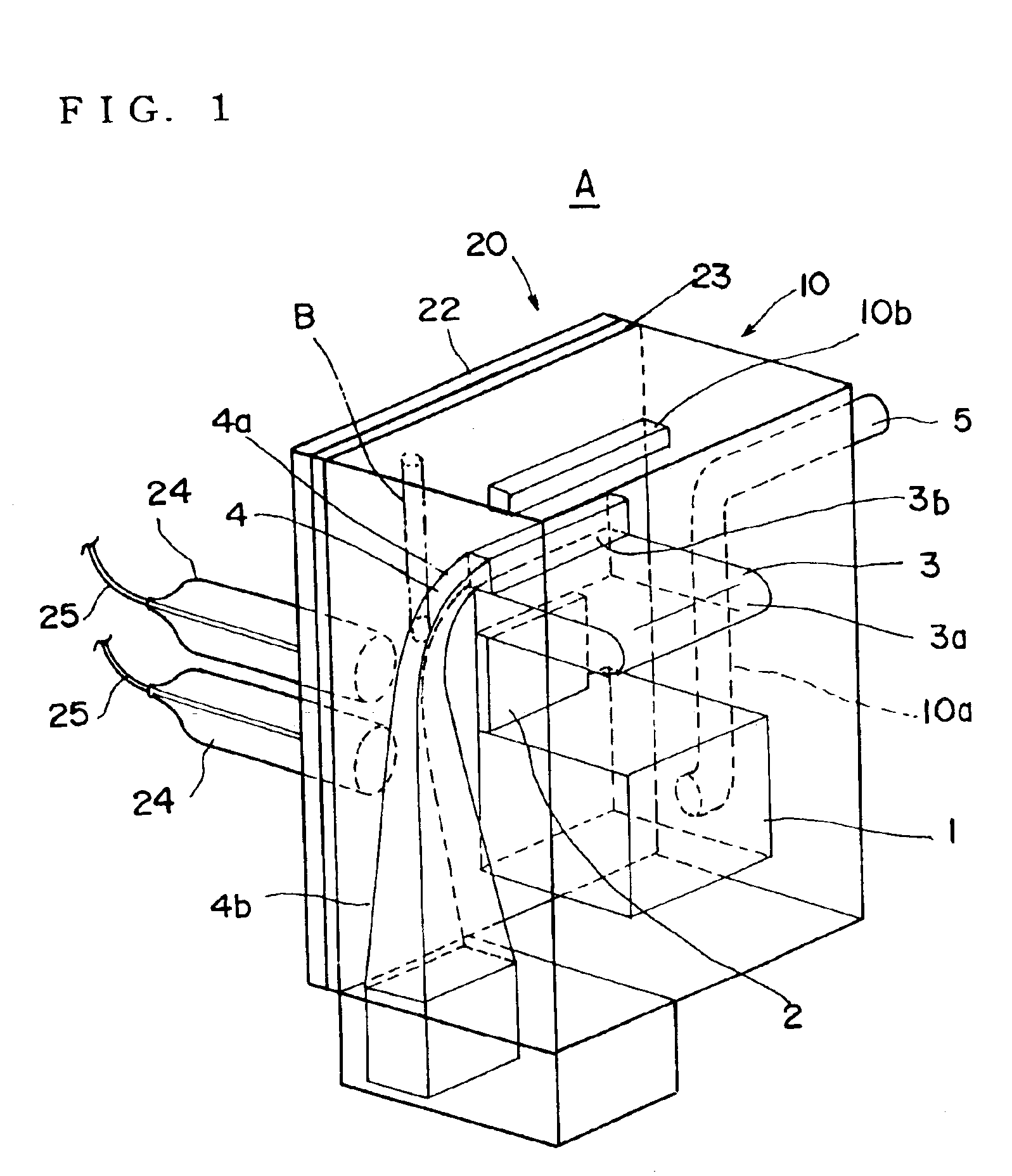
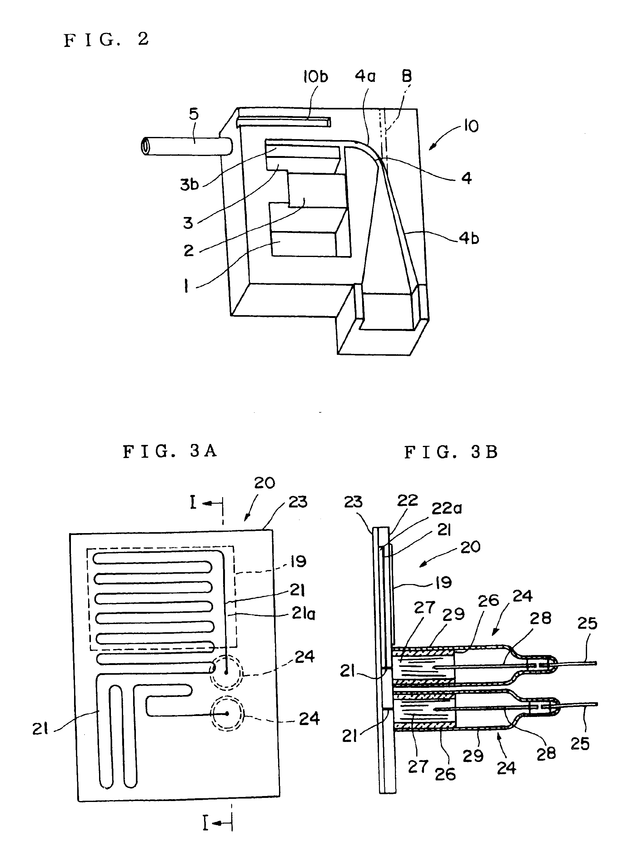
[0187]This embodiment is characterized in that the glass body 10 and the heater unit 20 are not integrated by welding but formed to be separable. In other words, as shown in FIG. 18A, the above-mentioned carbon wire heater body 21 is placed in the slot 22a of the glass plate 22, to which a glass plate 50 is welded so as to form the heater unit 20.

[0188]On the other hand, the liquid tank portion 1, the evaporator portion 2, the steam storage portion 3, the outlet port 3b, the passageway 4, and the thermocouple insertion hole 10b are formed in the glass body 10 as the recess. The glass plate 51 is welded to the recess side surface of this glass body 10.

[0189]While the above-mentioned heater unit 20 and glass body 10 are separately formed, as shown in FIG. 18B.

[0190]The heater unit 20 and the glass body 10 are surrounded by the thermal insulation material 37 as shown in ...


PUM


Abstract

A steam generating apparatus includes: a liquid tank portion 1 for storing a liquid; an evaporator portion 2 which is directly connected to the liquid tank portion, heats the liquid supplied from the liquid tank portion, and generates steam; a steam storage portion 3 which is directly connected to the evaporator portion, and stores the steam generated by the evaporator portion; a passageway 4 which is directly connected to the steam storage portion and outwardly passes the generated steam; a liquid pathway 10b which is connected to the liquid tank portion, and supplies the liquid; and a heater unit 20 which is provided on one side of the evaporator portion, and heats at least the evaporator portion. The liquid tank portion 1, the evaporator portion 2, the steam storage portion 3, the passageway 4, and the liquid pathway 10b are formed within an integral member of a translucent material.

Description

BACKGROUND OF THE INVENTION[0001]1. Field of the Invention[0002]The present invention relates to a steam generator, more particularly to a steam generator capable of generating steam in a short period of time. Further, the present invention relates to a mixer using the above-mentioned steam generator, more particularly to a mixer which generates a mixed gas by mixing steam with another material.[0003]2. Description of the Related Art[0004]A steam generating apparatus is used for a steam type inhaler which sucks up and sprays a liquid by means of using discharge of steam, an exhaust gas purifying apparatus as will be described later, etc., for example.[0005]Firstly, the steam generating apparatus used for the steam type inhaler will be described. In this type of steam type inhaler, a nozzle which discharges the steam is provided and an upper end of a sucking tube whose other end is put in a liquid within a liquid tank is disposed in the vicinity of the above-mentioned nozzle. Water i...

Claims


Application Information

Patent Timeline
Patent Type & Authority Patents(United States)
IPC IPC(8): A61M11/04A61M16/10A61M11/00F01N3/24
CPCA61M11/041A61M16/1075A61M16/109A61M11/042B23Q7/006B23Q7/02B23Q7/1494
Inventor TOYA, EIICHIKONN, TOMIO
Owner COVALENT MATERIALS CORP
Why Eureka
Try Eureka