
Control of flow through a vapor generator

a technology of vapor generator and control valve, which is applied in the direction of steam generation using hot heat carriers, machines/engines, lighting and heating apparatus, etc., can solve the problems of high temperature, high temperature, and high temperature of natural gas combustion or diesel fuel hot gases, so as to prevent excessive temperatures

Inactive Publication Date: 2005-11-08
NANJING TICA AIR CONDITIONING CO LTD
View PDF7 Cites 19 Cited by
  • Summary
  • Abstract
  • Description
  • Claims
  • Application Information

AI Technical Summary

Benefits of technology

[0013]Briefly in accordance with one aspect of the invention in the event of a failure of the ORC refrigerant circulation system the heat source is diverted from the ORC boiler to prevent excessive temperatures.
[0015]In accordance with another aspect of the invention, a diverter / ejector is placed between the heat source and the ORC, and the ejector is operated such that, during normal operation, the gases flow through the ejector and to the ORC, while at times when the ORC vapor generator temperature will fall below a certain level, the ejector is adjusted such that the exhaust gases flow from the heat source through the ejector and to ambient, while at the same time drawing ambient air through the ORC vapor generator, through the ejector and to ambient to thereby flush out the gases that would otherwise condense in the vapor generator.

Problems solved by technology

However, atmospheric emissions, such as nitrogen oxides (NOx) and particulates can be an issue with reciprocating engines.
Hot gases from the combustion of natural gases or diesel fuel can be very corrosive if allowed to condense on the heat transfer surfaces of the boiler tubes.
However, there are times during start up or maintenance when this constraint is not met and condensation and corrosion can occur.
Isolation of the boiler from the hot gas stream during these times could prevent condensation, but it is difficult and expensive to produce a high-temperature, low-leakage seal.
That is, if the exhaust gases being provided to the boiler are substantially in excess of 700° F., which can occur with gas turbine engines, then the refrigerant in the ORC will likely exceed a safe temperature threshold so as to cause decomposition of lubricant in the refrigerant, thereby forming coke which deteriorate boiler performance through excessive boiling and leads to oil loss of the system.
Also, the refrigerant itself might decompose when it sees temperatures of excess of 350° F.

Method used


Image

  • Control of flow through a vapor generator
  • Control of flow through a vapor generator
  • Control of flow through a vapor generator

Examples


Embodiment Construction

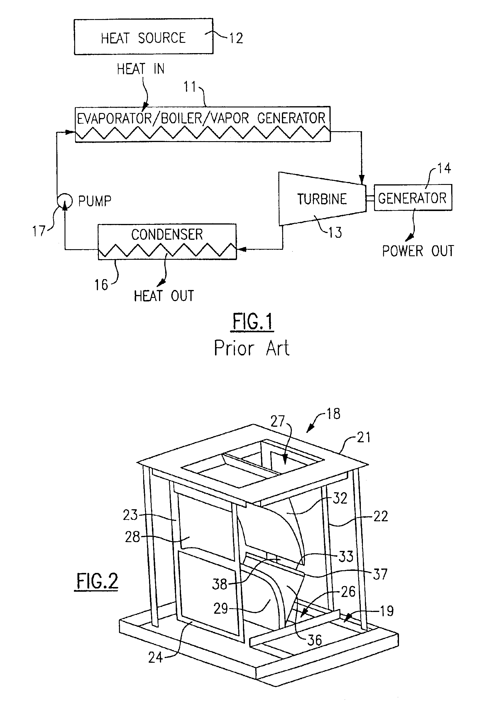
[0024]Referring now to FIG. 1, a typical Rankine cycle system is shown to include an evaporator / boiler / vapor generator 11 which receives heat from a heat source 12 to generate high temperature vapor and provide motive power to a turbine 13 which in turn drives a generator 14 to produce power. Upon leaving the turbine 13, the relatively low pressure vapor passes to the condenser 16 where it is condensed by way of heat exchange relationship with a cooling medium. The condensed liquid is then circulated to the evaporator by a pump 17 as shown to complete the cycle. The motive fluid in such Rankine cycle system is commonly water but may also be a refrigerant, in which case it is referred to as anorganic Rankine cycle (ORC).

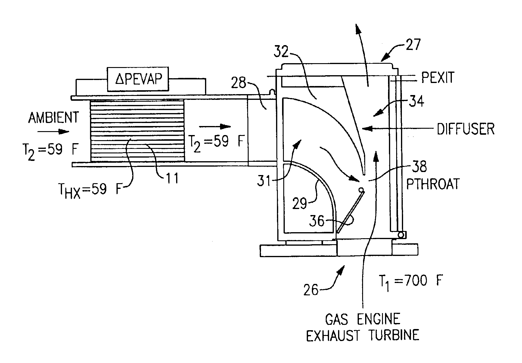
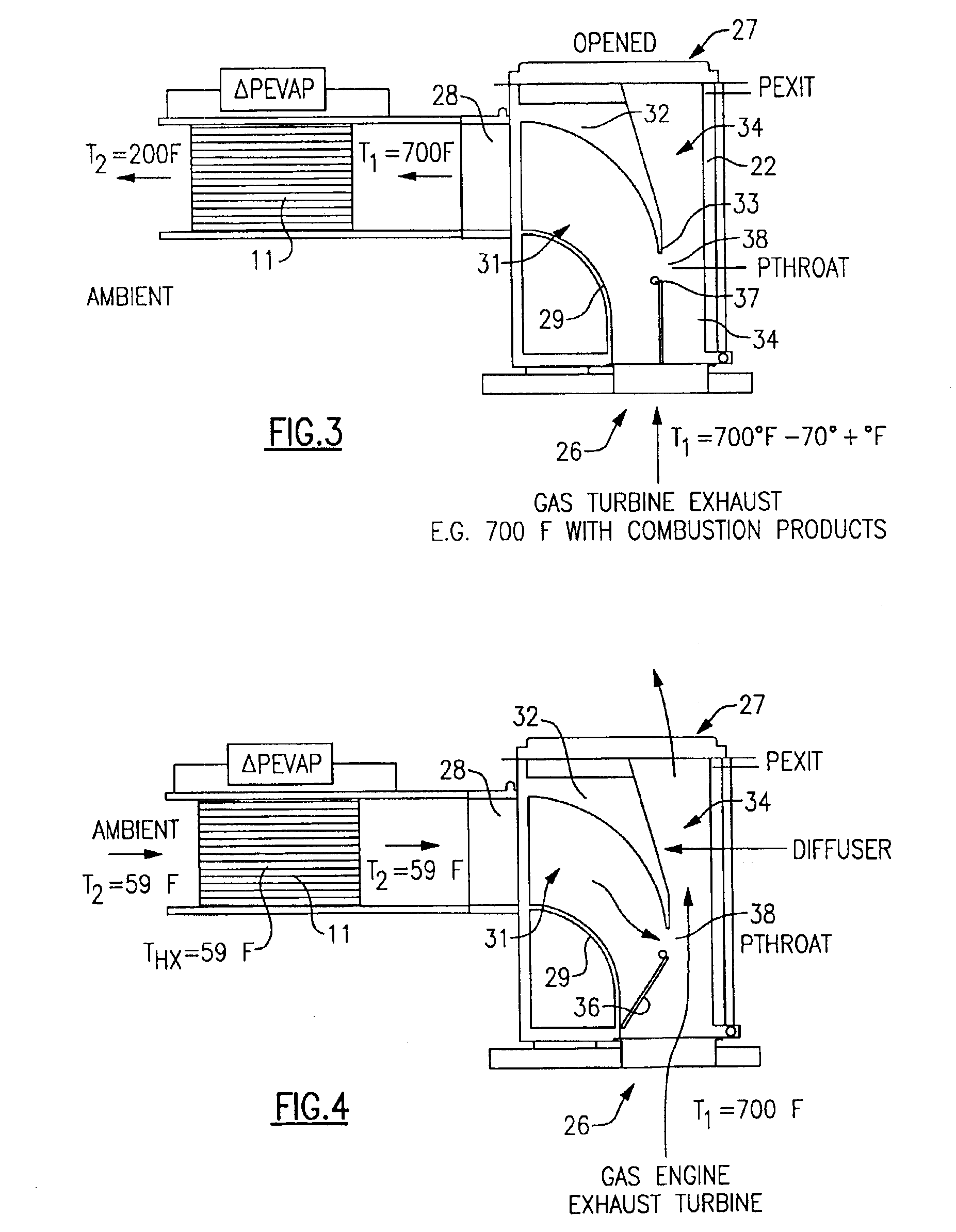
[0025]Such an organic Rankine cycle system is susceptible to three possible problems. Firstly, if the pump 17 fails, then the temperature of the refrigerant can rise to excessive levels. Secondly, if the gases from the heat source 12 are at too high a temperature, the...


PUM


Abstract

In a Rankine cycle system wherein a vapor generator receives heat from exhaust gases, provision is made to avoid overheating of the refrigerant during ORC system shut down while at the same time preventing condensation of those gases within the vapor generator when its temperature drops below a threshold temperature by diverting the flow of hot gases to ambient and to thereby draw ambient air through the vapor generator in the process. In one embodiment, a bistable ejector is adjustable between one position, in which the hot gases flow through the vapor generator, to another position wherein the gases are diverted away from the vapor generator. Another embodiment provides for a fixed valve ejector with a bias towards discharging to ambient, but with a fan on the downstream side of said vapor generator for overcoming this bias.

Description

FEDERALLY SPONSORED RESEARCH[0001]The U.S. Government has a paid-up license in this invention and the right in limited circumstances to require the patent owner to license others on reasonable terms as provided for by the term of Contract Nos.: FC02-00CH11060 and FC36-00CH11060 awarded by the Department of Energy.BACKGROUND OF THE INVENTION[0002]This invention relates generally to Rankine cycle systems and, more particularly, to a method and apparatus for controlling of the flow of a fluid through a vapor generator thereof.[0003]Power generation systems that provide low cost energy with minimum environmental impact, and that can be readily integrated into the existing power grids or rapidly sited as stand alone units, can help solve critical power needs in many areas of the U.S. Gas turbine engines and reciprocating engines are examples of such systems. Reciprocating engines are the most common and most technically mature of these distributing energy sources in the 0.5 to 5 MWe rang...

Claims


Application Information

Patent Timeline
IPC IPC(8): F01K25/00F01K25/08F22B1/18F22B1/00F22B35/00
CPCF01K25/08F22B1/1815F22B35/007
Inventor RADCLIFF, THOMAS D.
Owner NANJING TICA AIR CONDITIONING CO LTD
Features
  • Generate Ideas
  • Intellectual Property
  • Life Sciences
  • Materials
  • Tech Scout
  • Unparalleled Data Quality
  • Higher Quality Content
  • 60% Fewer Hallucinations
Learn More