
Target drive ventilation gain controller and method

a technology of gain controller and target drive, which is applied in the direction of valves, respirators, mechanical equipment, etc., can solve the problems of insufficient bio-physiological application of these theories, insufficient standardized analysis procedures for recording signals, and low amplitude of emg signals, etc., and achieves the effect of extreme pressure support levels

Inactive Publication Date: 2005-11-08
UNIV DE MONTREAL
View PDF31 Cites 63 Cited by
  • Summary
  • Abstract
  • Description
  • Claims
  • Application Information

AI Technical Summary

Benefits of technology

[0010]Another object of the present invention is to provide a method and a device capable of adjusting the degree of inspiratory assist in relation to the real need of the patient, i.e. only to compensate for the degree of incapacity of the patient.
[0016]a gain adjustment unit for increasing the value of the gain when the amplitude of the signal representative of respiratory drive output is higher than the amplitude the target drive signal and for decreasing the value of the gain when the amplitude of the signal representative of respiratory drive output is lower than the amplitude of the target drive signal.
[0021]increasing the value of the gain when the amplitude of the signal representative of respiratory drive output is higher than the amplitude of said target drive signal; and decreasing the value of the gain when the amplitude of the signal representative of respiratory drive output is lower than the amplitude of the target drive signal.
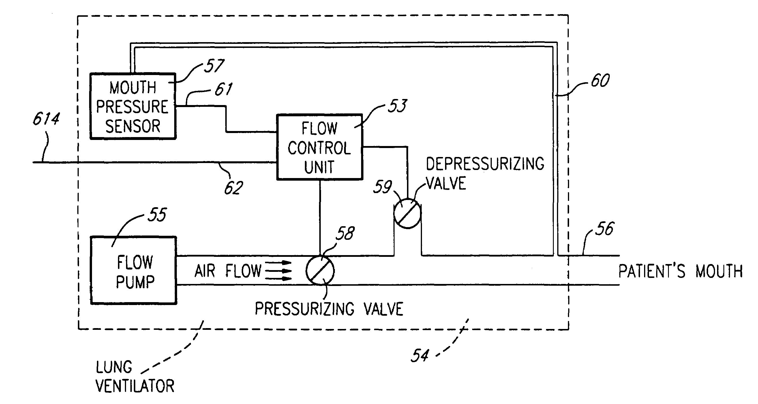
[0026]The advantage of Target drive ventilation is that this mode of ventilation does not depend on flow or volume measurements. A leaky ventilatory line will introduce a change in respiratory drive which will change the ventilatory assist in order to return the respiratory drive to its target level. Also, changes in the patient's metabolic or patho-physiological status which result in altered respiratory drive will be compensated. In contrast with present methods of controlling mechanical ventilators, an increase in respiratory assistance using a signal representative of respiratory drive output (e.g., an EMG signal) does not affect the efficiency with which these signals reliably control the ventilator (unless of course the disease affects the neuro-muscular function).

Problems solved by technology

Although the theoretical understanding is impressive, the bio-physiological application of these theories is, in practice, still deficient.
As an example, no standardized analysis procedure has been developed for recording signals produced by activation of several, different motor units, the so called interference wave pattern.
However, as this EMG signal is very low in amplitude, it is sensitive to numerous artifacts.
Prior art analysis of interference wave pattern signals usually comprises a time consuming, tedious manual determination of the quality of the signal through visual inspection of this signal in the time domain.
It is therefore not surprising to find that, in this technical field, independent studies evaluating the same questions have lead to different or even contradictory results.
Correct and repeated measurements of elastance and resistance are difficult to set up in an intensive care unit.
Moreover, in the presence of intrinsic positive end-expiratory pressure, the flow-volume controlled proportional assist ventilation may fail to trigger during whole breaths, and will definitively fail to trigger during at least the initial part of the inspiration which precedes the onset of flow; this period can last up to 300 ms in the case of a patient suffering from obstructive pulmonary disease.
Finally leakage in the system will influence and may disturb the performance of the flow controlled proportional assist ventilation.
These devices frequently cause leakage of gases such that measurement of flow and volume become erroneous.
Current technology is therefore often limited in its ability to detect and correct for these gas leaks and patients are at risk of becoming hyper- or hypo-ventilated.

Method used


Image

  • Target drive ventilation gain controller and method
  • Target drive ventilation gain controller and method
  • Target drive ventilation gain controller and method

Examples


Embodiment Construction

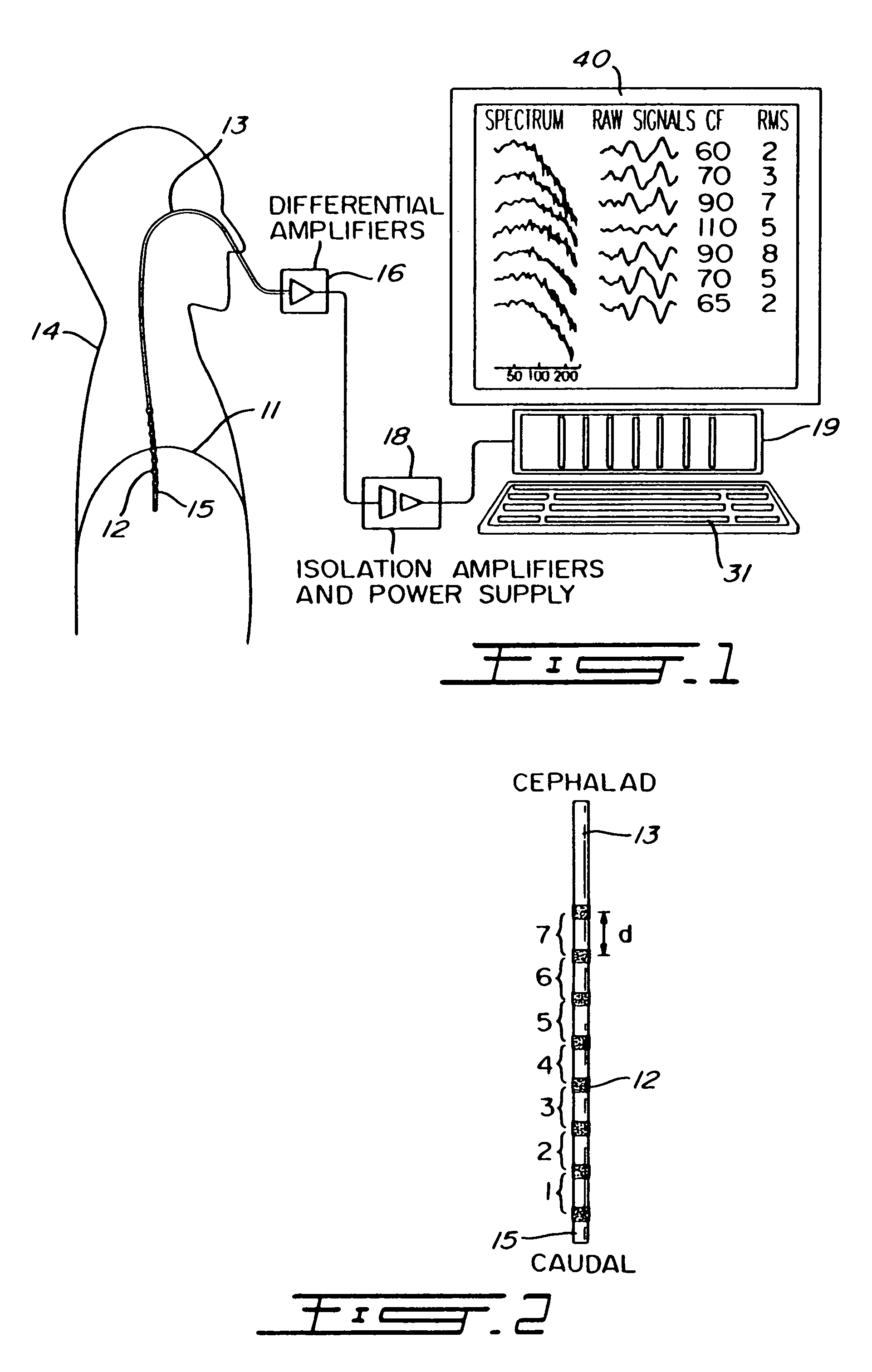
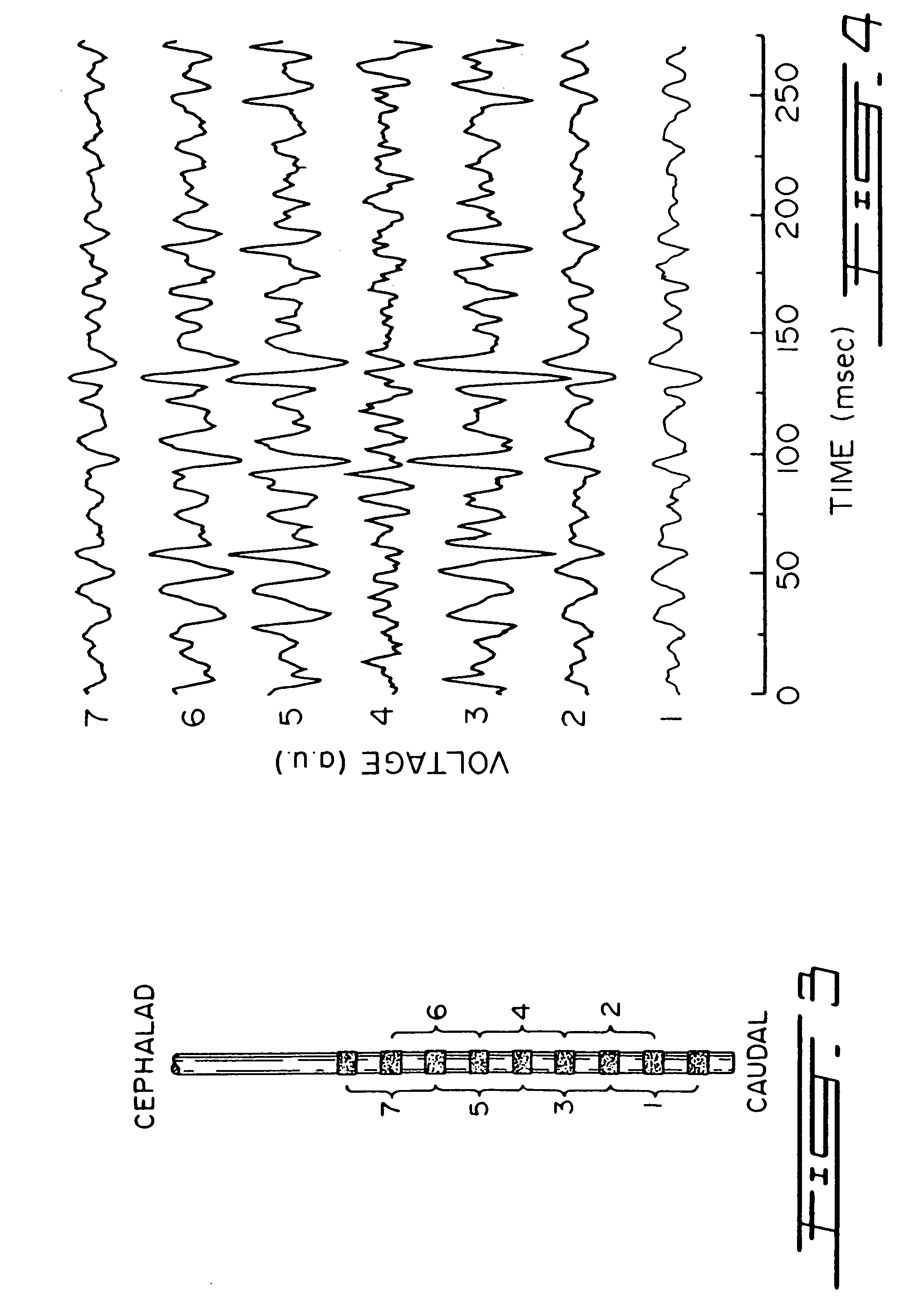
[0044]To measure EMG activity of the diaphragm 11 (EMGdi) of a human patient 14, an array of electrodes such as 12 (FIGS. 1 and 2) are mounted on the free end section 15 of an oesophageal catheter 13, with a constant inter-electrode distance d (FIG. 2). As shown in FIG. 1, the catheter 13 is introduced into the patient's oesophagus through one nostril or the mouth until the array of electrodes 12 are situated at the level of the gastro esophageal junction. The diaphragm 11 and / or the oesophagus slightly move during breathing of the patient 14 whereby the array of electrodes 12 also slightly moves about the diaphragm 11. As will be explained in the following description, automatic compensation for this displacement is provided.

[0045]To mount an electrode 12 on the free end section 15 of the catheter 13, stainless steel wire (not shown) may be wound around the catheter 13. The wound stainless steel wire presents a rough surface smoothed out by solder, which in turn is electroplated wi...


PUM


Abstract

A gain controller and method for controlling the value of a gain is used in conjunction with an electrode array for detecting a signal representative of respiratory drive output of a patient during inspiration, and a lung ventilator for assisting inspiration of the patient. The gain controller comprises an input for receiving the signal representative of respiratory drive output; a comparator for determining whether the signal representative of respiratory drive output is higher or lower than a target drive signal; and a gain adjustment unit for increasing the value of a gain when the amplitude of the signal representative of respiratory drive output is higher than the amplitude of the target drive signal and for decreasing the value of this gain when the amplitude of the signal representative of respiratory drive output is lower than the amplitude of the target drive signal. The gain is applied to the signal representative of respiratory drive output to produce an amplified respiratory drive output representative signal used for controlling the lung ventilator. The advantage of target drive ventilation is that this mode of ventilation does not depend on pressure, flow or volume measurements. A leaky ventilatory line will introduce a change in respiratory drive which will change the ventilatory assist in order to return the respiratory drive to its target level. Also, changes in the patient's metabolic or patho-physiological status which result in altered respiratory drive will be compensated.

Description

BACKGROUND OF THE INVENTION[0001]1. Field of the Invention[0002]The invention relates to a target driven inspiratory assist ventilation system.[0003]2. Brief Description of the Prior Art[0004]The physiological mechanisms which generate myoelectrical activity when a muscle contracts have been known and understood for a long time. In particular, how to record signals from the muscles is one of the most extensively, theoretically described topics in physiology. Although the theoretical understanding is impressive, the bio-physiological application of these theories is, in practice, still deficient. As an example, no standardized analysis procedure has been developed for recording signals produced by activation of several, different motor units, the so called interference wave pattern. The interference wave pattern signal (EMG signal) contains an immense quantity of bio-physiological information about the given neuro-muscular function. However, as this EMG signal is very low in amplitud...

Claims


Application Information

Patent Timeline
IPC IPC(8): A61M16/00A61N1/05
CPCA61M16/00A61N1/05A61M2210/1014A61M2230/08A61M2230/60A61M16/026
Inventor SINDERBY, CHRISTER
Owner UNIV DE MONTREAL
Learn More