Method and device for growing large-volume oriented monocrystals

Inactive Publication Date: 2005-11-29
HELLMA MATERIALS
View PDF10 Cites 15 Cited by
  • Summary
  • Abstract
  • Description
  • Claims
  • Application Information

AI Technical Summary

Benefits of technology

[0021]The bottom of the crucible is preferably provided with a downward protruding well which serves to receive a seed crystal of-a desired orientation. The seed crystal well is preferably disposed in the middle of the bottom, namely at the tip of the cone or pyramid. In a preferred embodiment of the invention, the seed crystal well has, particularly at its lower end, a cooling element. This cooling element is preferably a water-filled cooling element which during the melting of the crystal raw material protects the seed crystal present in the well from premature incipient or complete melting. In a preferred embodiment of the invention, the cooling element is heatable.
[0035]The phase boundary needed for the crystal growing according to the invention is obtained by preventing the formation of a lateral, namely radial heat flow. This is achieved with the aid of lateral elements, particularly elements disposed around the walls of the melting vessel. Such elements preferably consist of a supporting heater and / or an insulating material. It is particularly preferred to dispose along, and at a distance from, the side walls heating elements which serve exclusively to maintain the temperature. In this case, the interspace between the melting vessel and the heater disposed at a distance therefrom is filled with insulating material which on the one hand prevents lateral heat removal and thus the formation of a radial temperature gradient and, on the other, keeps the supporting heater from causing local overheating in the melting vessel. In essence, the supporting heater serves to counteract any heat loss through the insulating jacket thus supporting the maintenance of radial planarity of the temperature profile.

Problems solved by technology

Such methods, however, are meant primarily for laboratory-scale work and not for large-scale industrial production.
The drawback of this method is that cooling produces relatively large temperature changes in the crystal resulting in stress-induced anisotropy.
Nevertheless, oriented monocrystals usually do not exhibit homogeneous optical and mechanical properties.
This, however, creates major problems in the production of large monocrystals, because during their growth such crystals spontaneously change their orientation, namely the position of their crystal axis.
Until now, while it was possible to produce crystals exhibiting some of these properties, it was not possible to grow large-volume uniformly oriented crystals that are free of convergences, are optically highly homogenous, exhibit high transmission and, in addition, do not discolor when exposed to a strong radiation source.
This gave very low yields, however, namely only about 6-8% of the growing attempts gave a satisfactory crystal size.
Because such crystal growing methods involve a process with a running time of approximately 6 weeks, and the number of such growing units is limited because of cost reasons, only low yields were achieved.
Moreover, it was not possible by use of previously employed methods to produce large-volume monocrystals, particularly monocrystals extending far in all three directions in space, namely preferably round crystals with a diameter of >200 mm and a height of >100 mm, because such dimensions regularly lead to block formation within the crystal volume, namely a reorientation of the crystal axes takes place.
Moreover, it has thus far not been possible to obtain satisfactorily such large crystals also in optically highly homogeneous form, namely so that their light refraction is the same in all regions.
Another problem with such crystals is their radiation resistance, namely their ability not to undergo discoloration when exposed to a strong radiation source, for example a laser.
This problem causes a decrease in yield, for example in the large-scale production of wafers.
Although by this method it is possible to produce large oriented monocrystal plates, said plates do not adequately extend in all three directions in space.

Method used


Image

  • Method and device for growing large-volume oriented monocrystals
  • Method and device for growing large-volume oriented monocrystals
  • Method and device for growing large-volume oriented monocrystals

Examples


example 1

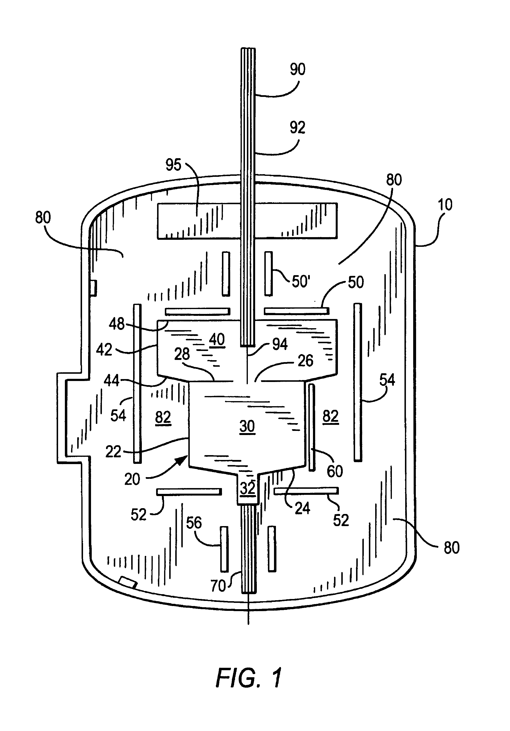
[0054]To produce a calcium fluoride monocrystal, inner space 30 of melting vessel 20 was filled with a calcium fluoride mixture, which in addition contained scavenger materials with high affinity for oxygen, such as PbF2, SnF2 or CdF2. The device was then closed with a cover not shown in FIG. 1 and was flushed with nitrogen as inert gas to remove the undesirable atmospheric oxygen. A vacuum of 10−4 mbar (10−2Pa) was then applied and, while cooling the seed crystal well 32, cover heater 50, 50′, bottom heater 52 and optionally jacket heater 54 were put in place and slowly heated to 1450° C. over a period of several hours. The melt was then homogenized at this temperature for five days while maintaining convection in it. After the homogenization, the bottom heater temperature was reduced to a temperature of 1200° C., and the seed crystal was carefully melted with the aid of seed crystal well heater 56. After turning off the seed crystal well heater, cover heater 50, 50′ was kept const...


PUM


Abstract

In the method for growing large-volume monocrystals crystal raw material is heated in a melting vessel with heating elements to a temperature above its melting point until a melt is formed. A monocrystal is then formed on the bottom of the melting vessel by lowering the temperature at least to the crystallization point. A solid / liquid phase boundary is formed between the monocrystal and the melt. The monocrystal grows towards the melt surface in a direction that is perpendicular to the phase boundary. A vertical axial temperature gradient is produced and maintained between the bottom of the melting vessel and its upper opening and heat inflow and / or heat outflow through side walls of the melting vessel is prevented, so that the solid / liquid phase boundary has a curvature radius of at least one meter. A crystal-growing device for performing this process is also described.

Description

BACKGROUND OF THE INVENTION[0001]The invention relates to a method for growing large-volume monocrystals of uniform orientation from a melt, to a device for carrying out this method and to the use of crystals prepared in this manner.[0002]Monocrystals are characterized by the fact that they have a uniform orientation throughout their entire volume which is a prerequisite for high optical homogeneity within the entire crystal volume. For this reason, they are eminently suited for use in the optical industry or as starting material for optical components in deep-ultraviolet [DUV] photolithography, for example for steppers or excimer lasers.[0003]The growing of monocrystals from a melt is in itself known. Text books about crystal growing, for example “Kristallzüjchtung” [The Growing of Crystals] by K. Th. Wilke and J. Bohm, which has 1088 pages, describe a wide variety of different methods for crystal growing of which the most common techniques will be mentioned briefly in the followin...

Claims


Application Information

Patent Timeline
IPC IPC(8): G03F7/20C30B11/00C30B29/12H01L21/027
CPCC30B11/00C30B11/003C30B29/12Y10T117/10Y10S117/90
Inventor WEHRHAN, GUNTHERELZNER, PETERMOERSEN, EWALDSCHATTER, RICHARDAXMANN, HANS-JOERGREICHARDT, THORSTEN
Owner HELLMA MATERIALS
Why Eureka
Try Eureka