Rolling bearing unit

a technology of rolling bearings and components, applied in the direction of instruments, measuring devices, force/torque/work measurement apparatus, etc., can solve the problems of troublesome replacement of these parts, increased cost of rolling bearing units, and difficulty in enhancing the detection precision of distortion gauges, so as to prolong the life of rolling bearings and facilitate replacement of members , the effect of reducing the length of the harness or the cable for transmitting the signal

Inactive Publication Date: 2005-12-06
NSK LTD
View PDF12 Cites 26 Cited by
  • Summary
  • Abstract
  • Description
  • Claims
  • Application Information

AI Technical Summary

Benefits of technology

[0023]According to the rolling bearing unit of the present invention with this constitution, a detected value of load represented by an output signal outputted from the detecting portion of the sensor device or a signal obtained by processing the output signal can be outputted to an output section of an output device provided on a receiving device side. In this arrangement, the operator can easily judge how much the machine provided with this rolling bearing is deteriorated. Further, by adjusting the axial load imposed axially on the member in which the inner ring or outer ring is fitted depending on the detected value of load using an adjustor, the axial load imposed on the rolling bearing can be adjusted to a proper value, making it possible to prolong the life of the rolling bearing. Moreover, the harness or cable for transmitting the signal can be shortened, making it possible to easily replace the member in which the inner ring or outer ring is fitted or the rolling bearing. Further, in the case where the sensor device is provided with the entire transmitting device, it is not necessary to connect the harness or cable to the supporting member by which the sensor device is supported, making the replacement easier. This arrangement also makes it possible to prevent the breaking of the harness or cable.
[0024]Further, the supporting member is fitted in and supported by the member in which the outer ring or inner ring as a fixed ring is fitted in such an arrangement that the supporting member is opposed to the axial end of the outer ring or inner ring as the fixed ring. The sensor device, which comprises the detecting portion for detecting the load imposed axially on the supporting member by the outer ring or inner ring as the fixed ring and at least the part of the transmitting device for transmitting the output signal outputted from of the detecting portion or the signal obtained by processing the output signal as a wireless signal, is supported by a part of the supporting member. In this arrangement, the invention can easily detect the load imposed axially on the rolling bearing to a good precision.
[0025]Moreover, according to the rolling bearing unit of the present invention, it is not necessary that a plurality of members which are separate bodies be combined to form the supporting member. In this arrangement, the production of the rolling bearing unit with the sensor device can be simplified. Further, a side surface, which is provided on a part of the supporting member for butting to a mating member disposed axially opposed to the supporting member, can be positioned on the same virtual plane extending perpendicular to the central axis of the supporting member without the necessity of troublesome assembly. In this arrangement, the detecting precision of the sensor device can be enhanced while preventing cost rise.
[0026]Further, according to the rolling bearing unit of the present invention, the plurality of protrusions for butting to the mating member may be provided at positions where the phase of one of protrusions in the circumferential direction of the supporting member coincides with that of the detecting portion of the sensor device provided on a part of the supporting member. If the sensor device has a plurality of the detecting portions, the circumferential phases of protrusions coincide with those of the detecting portions. In this arrangement, the detecting precision of the sensor device can be enhanced. Moreover, the area of the forward end of the plurality of protrusions, which are subject to load imposed by the mating member, among the parts of the supporting member can be reduced, making it possible to enhance the detecting precision of the sensor device.
[0027]Further, according to the rolling bearing unit of the present invention, an external inputting device is provided with a transmitting device for transmitting data to be recorded in the memory constituting the electronic tag as a wireless signal. In this arrangement, data representing information to be managed with regard to the rolling bearing unit with the sensor device such as production step, flow, sale, use, failure and repair can be recorded in the memory without connecting the electronic tag and the external inputting device to the harness or cable. Moreover, the external outputting device such as portable data terminal is provided with a receiving portion for receiving the wireless signal generated by the electronic tag. In this arrangement, date recorded in the memory can be outputted as necessary, making it possible to easily manage the data to be managed. Further, in the case where the rolling bearing unit with the sensor device is no longer required, the data to be managed can be utilized to reuse it easily. Moreover, by arranging the rolling bearing unit with the sensor device such that data representing the material and disassembly step of the rolling bearing unit with the sensor device can be freely recorded in the memory, the disassembly of the rolling bearing unit with the sensor device and the classification of parts thus produced into reusable resources can be automated, facilitating complete recycling that produces no waste parts.

Problems solved by technology

Thus, the replacement of these parts becomes troublesome.
Accordingly, it is difficult to enhance the detection precision of the distortion gauges 12, 12 while preventing the rise of cost of the rolling bearing unit with the sensor device.
In this arrangement, the load imposed axially on the rolling bearing can be difficultly detected to a good precision.

Method used


Image

  • Rolling bearing unit
  • Rolling bearing unit
  • Rolling bearing unit

Examples


Embodiment Construction

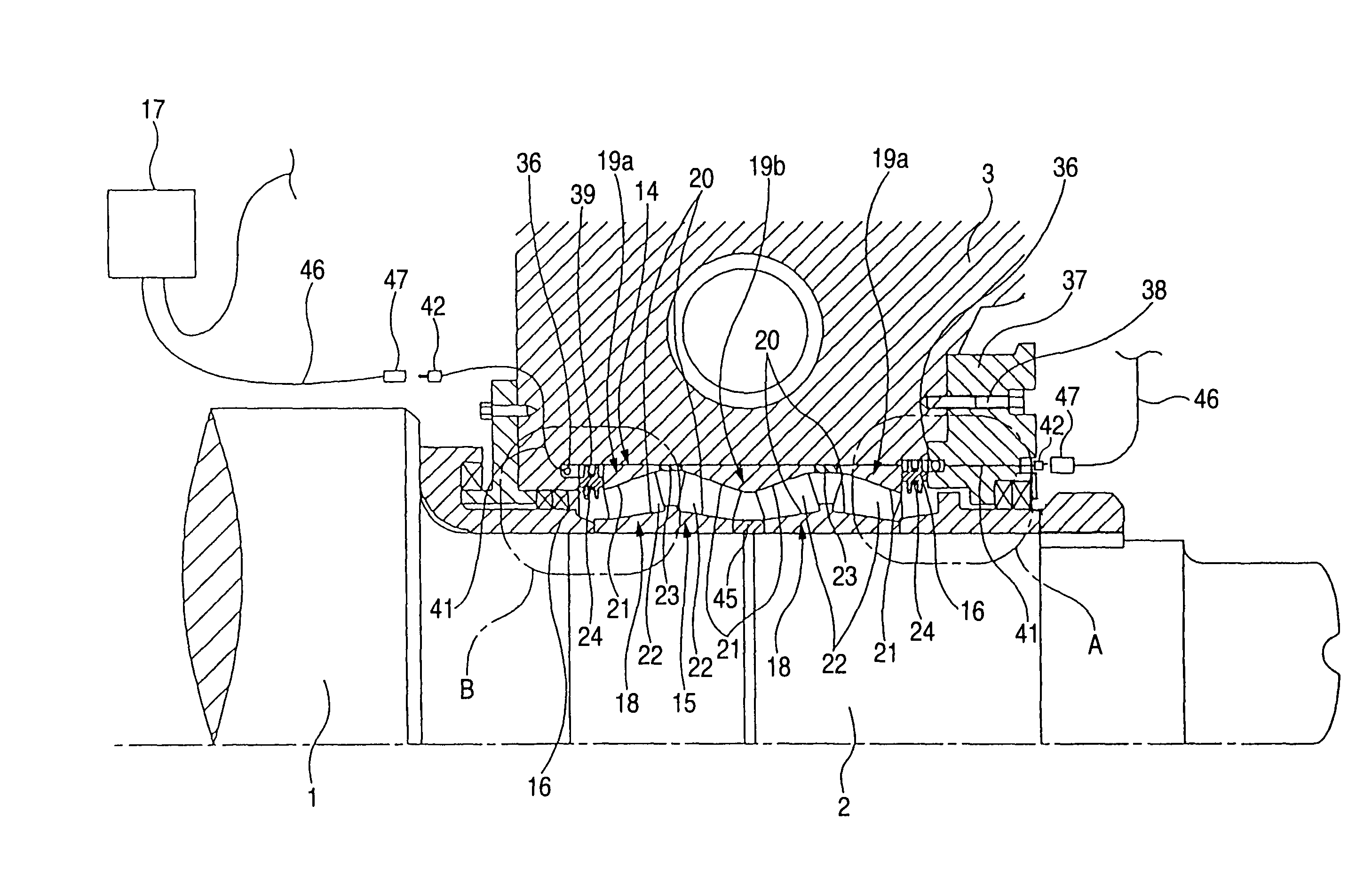
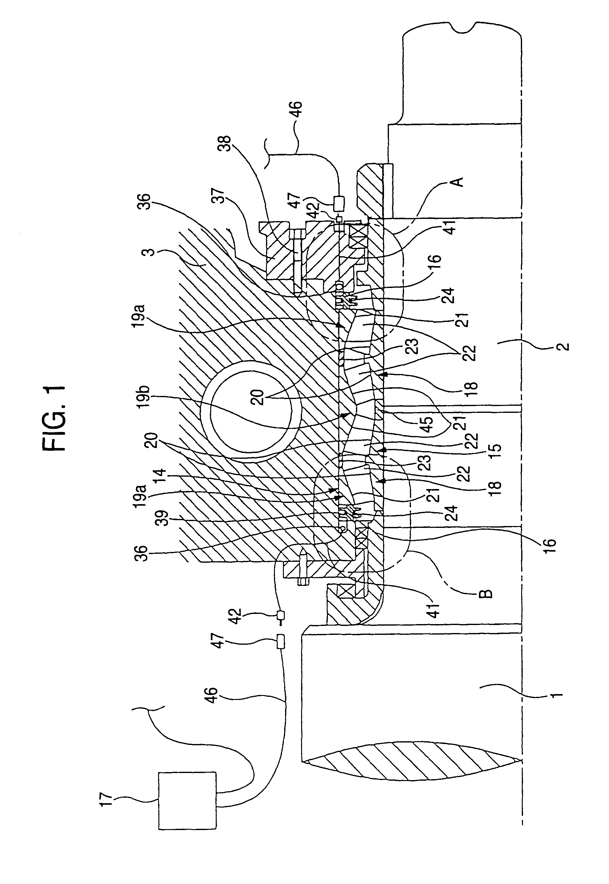
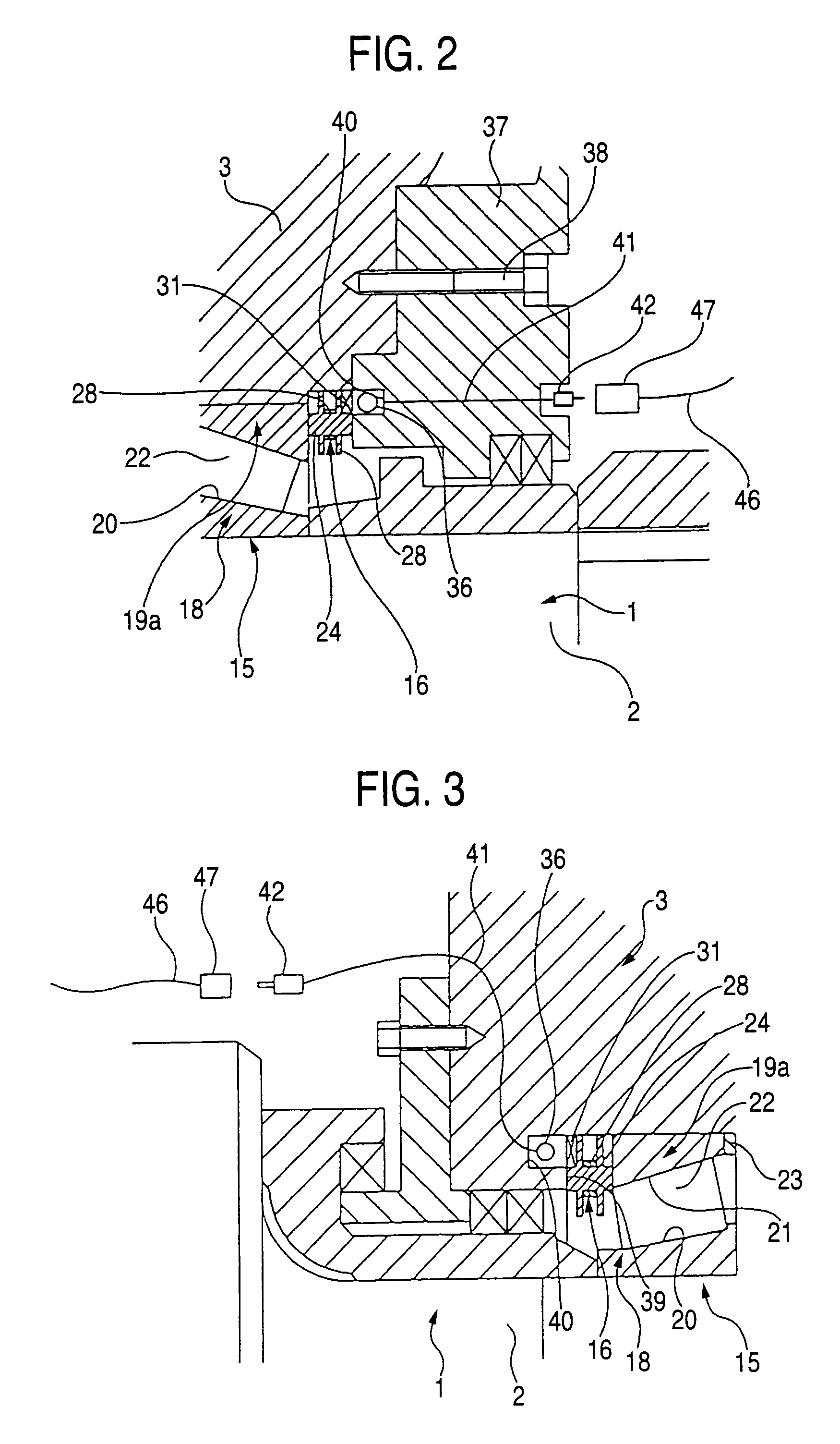
[0042]FIGS. 1 to 7 each show a rolling bearing unit with a sensor device according to a first embodiment of the present invention. In the first embodiment, a rolling bearing unit 14 with a sensor device is incorporated in a rotary supporting portion on both axial ends of a rolling roller 1 in a rolling mill for rolling a metallic material such as steel. In some detail, a roll neck 2 is provided in the central portion on the both axial ends of the rolling roller 1, and rotatably supported by a four-row tapered roller bearing 15 inside a housing 3 which does not rotate even during use. The rolling bearing unit 14 comprises the four-row tapered roller bearing 15, the pair of sensor devices 16, 16, a pair of second coils 36, 36 and an external inputting / outputting device 17 (FIG. 6). The four-row tapered roller bearing 15 comprises a pair of inner rings 18, 18, three outer rings 19a, 19b, conical convex inner ring raceways 20, 20, conical concave outer ring raceways 21, 21, and a plural...


PUM

PropertyMeasurementUnit
circumferenceaaaaaaaaaa
diameteraaaaaaaaaa
shape precisionaaaaaaaaaa

Abstract

A four-row tapered roller bearing is incorporated in the clearance between the inner surface of a housing and the outer surface of a rolling roller. A pair of supporting members supporting sensor devices are fitted in and supported by a part of the inner surface of the housing in such a manner that they are opposed to the ends of outer rings of the four-row tapered roller bearing disposed close to the both axial ends thereof. The sensor devices each comprise a distortion gauge as a detecting portion and a first coil for transmitting as a wireless signal a signal obtained by processing an output signal outputted from the distortion gauge. A second coil for receiving the wireless signal transmitted by the first coil is retained on a part of a member other than the supporting members.

Description

BACKGROUND OF THE INVENTION[0001]1. Field of the Invention[0002]The present invention relates to a rolling bearing unit including a rolling bearing and a sensor device, which bears various rolls of rolling mill for iron and steel, paper manufacturing machine, etc. rotatably with respect to a fixed portion and detects the load axially imposed on the rolling bearing (axial load) to judge the deterioration of the machines or adjust the axial load so as to prolong the bearing life.[0003]2. Description of the Related Art[0004]For example, a rolling bearing for roll neck which bears a roller of rolling mill for iron and steel is subject to not only radial load but also axial load during operation. This axial load varies with the degree of deterioration of the rolling mill. Accordingly, the degree of deterioration of the rolling mill can be judged by detecting the axial load. Further, by adjusting the axial load imposed on a member in which an outer ring or inner ring constituting the roll...

Claims


Application Information

Patent Timeline
Patent Type & Authority Patents(United States)
IPC IPC(8): G01L5/12B21B31/07B21B33/00B21B38/00F16C19/38F16C19/52F16C35/07F16C41/00G01L5/00G08C17/02G08C19/38
CPCB21B31/07F16C13/02F16C19/388F16C41/008G08C19/38F16C19/522B21B33/00B21B38/00B21B2038/002B21B2203/38F16C2322/12
Inventor SATO, YUKIOKONNO, KATSUHIRO
Owner NSK LTD
Why Eureka
Try Eureka