Oxidation structure/method to fabricate a high-performance magnetic tunneling junction MRAM

a high-performance, magnetic tunneling junction technology, applied in the direction of solid-state devices, instruments, transportation and packaging, etc., can solve the problems of affecting the overall homogeneity and stoichiometry of the barrier layer, the diffusion front does not proceed at a uniform rate or with a uniform spatial dependence, and the energetic oxygen plasma ions may damage the underlying ferromagnetic material of the lower (pinned) electrode. , to achieve the effect of improving

Active Publication Date: 2005-12-13
TAIWAN SEMICON MFG CO LTD +1
View PDF5 Cites 54 Cited by
  • Summary
  • Abstract
  • Description
  • Claims
  • Application Information

AI Technical Summary

Benefits of technology

[0025]In both (A) and (B), BL stands for “bottom lead,” SE stands for “sputter etching,” OSL stands for “oxygen surfactant layer” and ROX stands for “radical oxidation.” The mild ROX process applied to oxidize the upper surface of the Al layer also enhances the overall homogeneity and stoichiometry of the barrier layer, making the interfacial regions particularly high quality. It is further noted that stack (A) includes a CoFe(25%) layer on which the OSL is formed, while stack (B) includes a composite CoFe(10%)-NiFe(60%) layer on which the OSL is formed.
[0026]After the stack configurations are formed, they are annealed for approximately 5 hours in a 10 kOe (kilo-Oersted) magnetic field to set the pinning fields. This annealing process further homogenizes the oxygen in the barrier layer to improve its integrity. In this regard, the smaller grain size already produced in the Al layer as a result of the OSL enhances the homogenization process of the anneal.

Problems solved by technology

When the oxidation method used is plasma oxidation, the energetic oxygen plasma ions may damage the underlying ferromagnetic material of the lower (pinned) electrode.
Consequently, the oxygen diffusion front does not proceed at a uniform rate or with a uniform spatial dependence through the deposited aluminum layer.

Method used


Image

  • Oxidation structure/method to fabricate a high-performance magnetic tunneling junction MRAM
  • Oxidation structure/method to fabricate a high-performance magnetic tunneling junction MRAM
  • Oxidation structure/method to fabricate a high-performance magnetic tunneling junction MRAM

Examples


Embodiment Construction

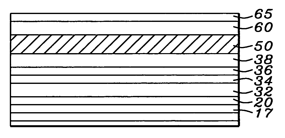
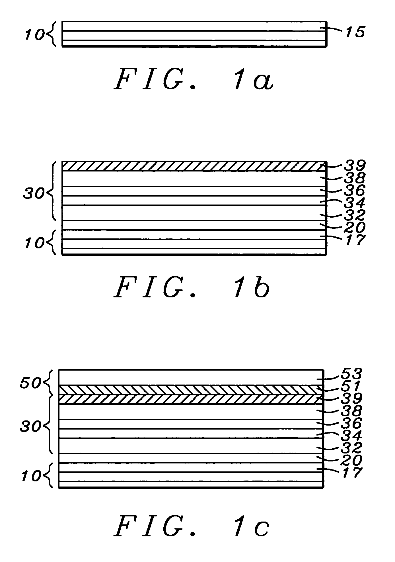
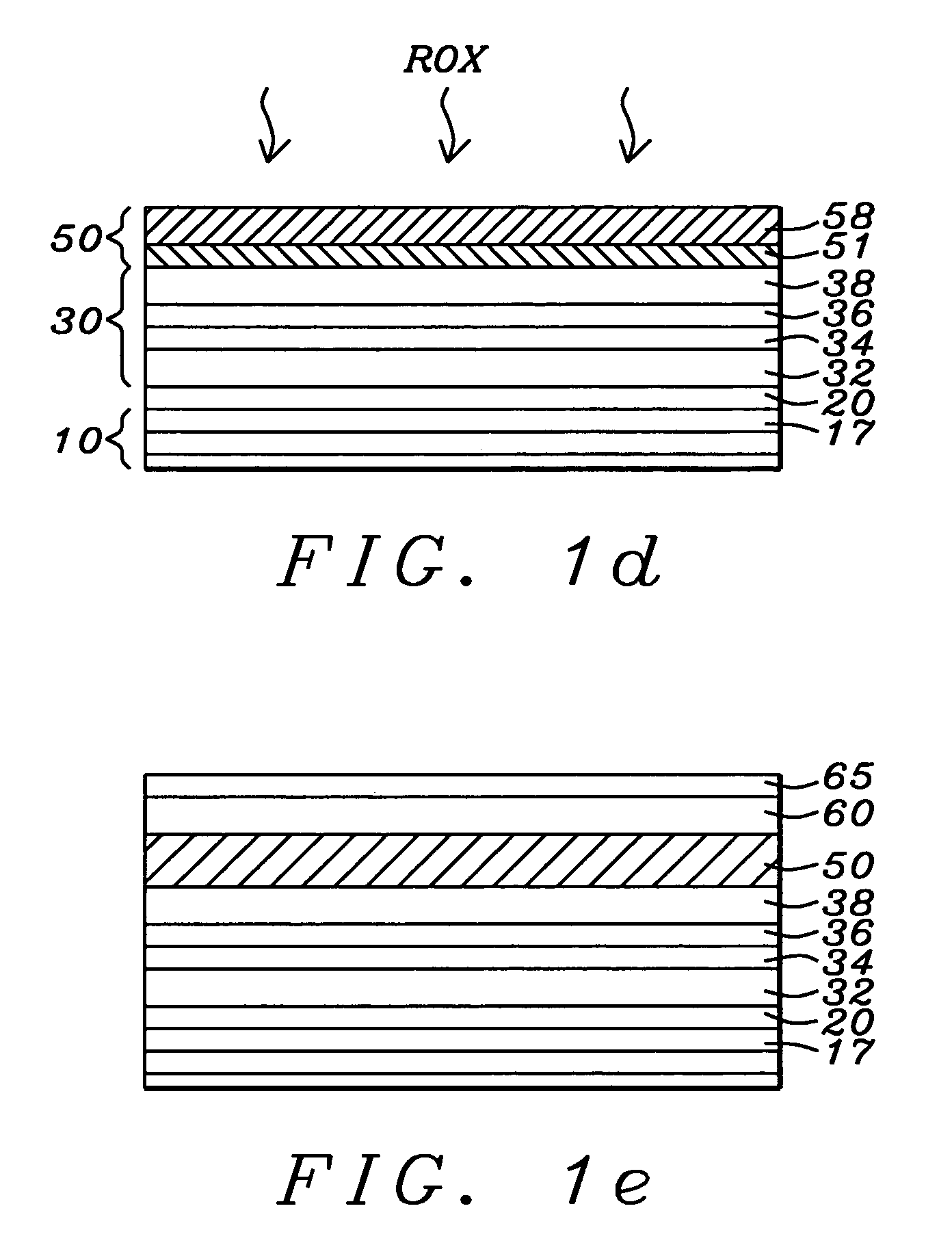
[0028]Referring first to FIG. 1a, there is seen in a schematic cross section an initial stage of a preferred embodiment of the invention, the formation of a single MRAM element, which can be a part of an array of such elements. It is to be understood that in the embodiments to be disclosed in what follows, all layer depositions take place in a high vacuum PVD chamber suitable for depositing thin layers by sputtering and oxidation processes take place in a separate plasma oxidation chamber. In these embodiments the system was a commercially available Anelva 7100 system which includes both such chambers, but other comparable systems are also suitable.

[0029]There is shown first a substrate (10), which in this embodiment is a lower conducting lead (the bit line, for example) on which the MRAM element will be formed. It is further understood that the single MRAM element can be one of an array of such elements and that such element or array may be further connected to associated circuitry...


PUM


Abstract

An MTJ (magnetic tunneling junction) MRAM (magnetic random access memory) has a tunneling barrier layer of substantially uniform and homogeneous Al2O3 stoichiometry. The barrier layer is formed by depositing Al on a CoFe layer or a CoFe—NiFe bilayer having an oxygen surfactant layer formed thereon, then oxidizing the Al by radical oxidation. The underlying surfactant layer contributes oxygen to the bottom surface of the Al, forming an initial amorphous Al2O3 layer. This layer produces small, uniform grains in the remaining Al layer, which promotes a uniform oxidation of the Al between its upper and lower surfaces by the subsequent radical oxidation. A final annealing process to set a pinned layer magnetization enhances the homogeneous oxidation of the layer.

Description

RELATED PATENT APPLICATION[0001]This application is related to Ser. No. 10 / 371,841, filing date is Feb. 10, 2003, patent number is U.S. Pat. No. 6,703,654, Ser. No. 10 / 768,917, filing date is Jan. 30, 2004, Ser. No. 10 / 661,038, filing date is Sep. 12, 2003, Ser. No. 10 / 844,171, filing date is May 12, 2004 and Ser. No. 10 / 849,310, filing date is May 19, 2004, assigned to the same assignee as the current invention.BACKGROUND OF THE INVENTION[0002]1. Field of the Invention[0003]This invention relates generally to magnetic tunneling junction (MTJ) MRAMs and more particularly to the use of an oxidation process that leads to a smooth bottom electrode and resulting superior performance properties.[0004]2. Description of the Related Art[0005]The magnetic tunneling junction device (MTJ device) is essentially a variable resistor in which the relative orientation of magnetic fields in an upper and lower magnetized electrode controls the flow of spin-polarized tunneling electrons through a very...

Claims


Application Information

Patent Timeline
Patent Type & Authority Patents(United States)
IPC IPC(8): H01L27/105G11C11/34G11C16/04H01L21/00H01L21/8246H01L43/08H01L43/12
CPCH01L43/08H01L43/12H10N50/01H10N50/10H04M1/04B60R11/0241
Inventor HORNG, CHENG T.TONG, RU-YING
Owner TAIWAN SEMICON MFG CO LTD
Why Eureka
Try Eureka