Gain normalization for automatic control of lightwave emitters

a technology of automatic control and lightwave emitters, applied in semiconductor lasers, electrical devices, laser details, etc., can solve the problems stability problems, and the effect of reducing the power of optical output signals, improving the control of modulated light sources, and optimizing response time, bandwidth, or steady-state accuracy

Inactive Publication Date: 2005-12-13
ANALOG DEVICES INT UNLTD
View PDF12 Cites 23 Cited by
  • Summary
  • Abstract
  • Description
  • Claims
  • Application Information

AI Technical Summary

Benefits of technology

[0020]It is therefore an object of the present invention to provide circuits and methods for improving control of modulated light sources.
[0021]This and other objects of the present invention are accomplished in accordance with the principles of the present invention by providing circuits and methods automatically controlling lightwave emitters. A control system is provided that includes a variable gain circuit for automatical

Problems solved by technology

In addition to changes in average optical output power, a change in slope efficiency also adversely affects extinction ratio.
One problem with system 10, however, is that variations in transfer ratio (i.e., the product of slope efficiency and detector sensitivity) reduce its ability to maintain the power of optical output signal 115 constant.
High loop gain is required for high accuracy, but excessive loop gain causes stability problems.
If the loop gain is too low, however, large errors will be encountered in controlling average optical power.
Thus, as transfer rat

Method used


Image

  • Gain normalization for automatic control of lightwave emitters
  • Gain normalization for automatic control of lightwave emitters
  • Gain normalization for automatic control of lightwave emitters

Examples


Embodiment Construction

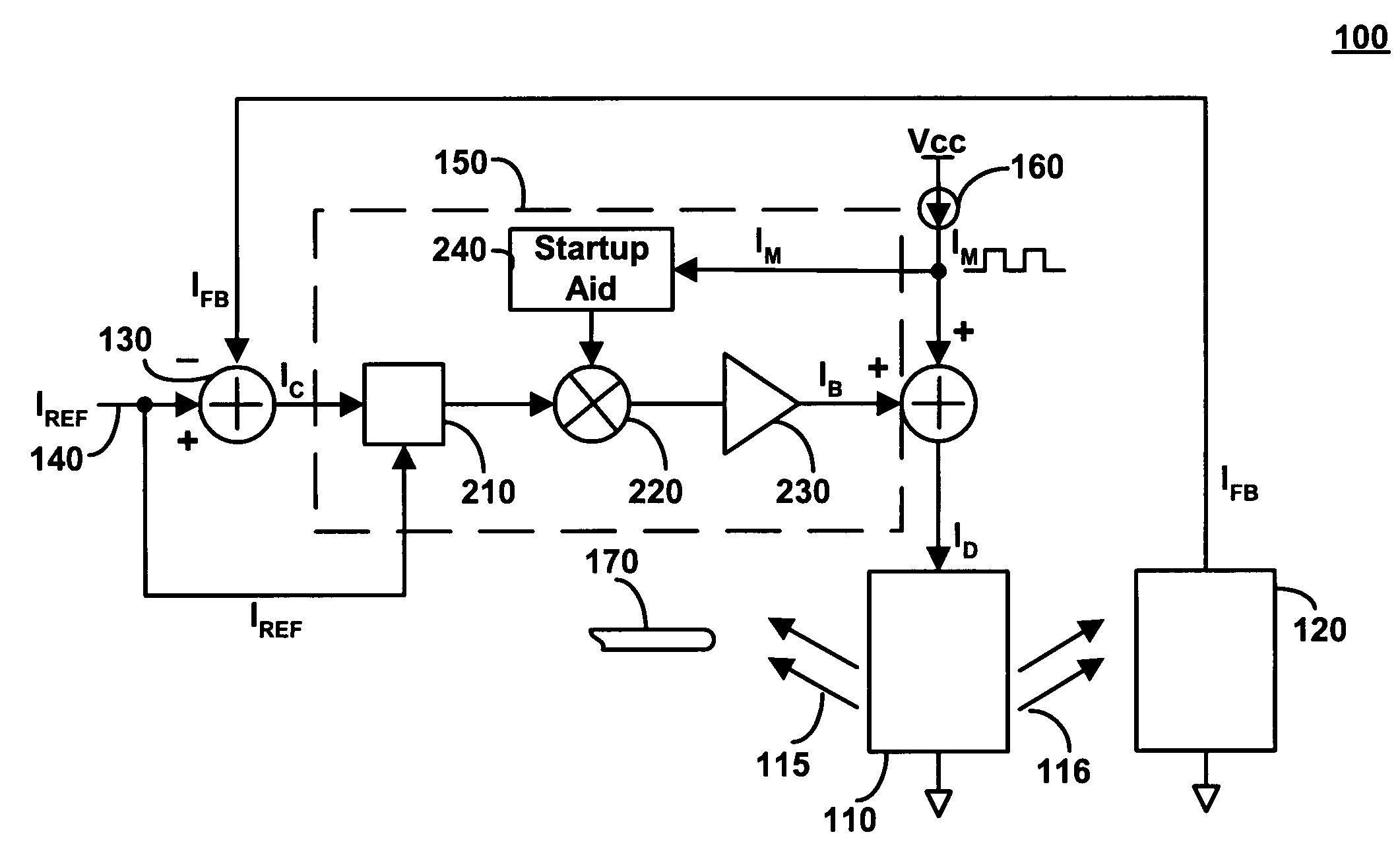
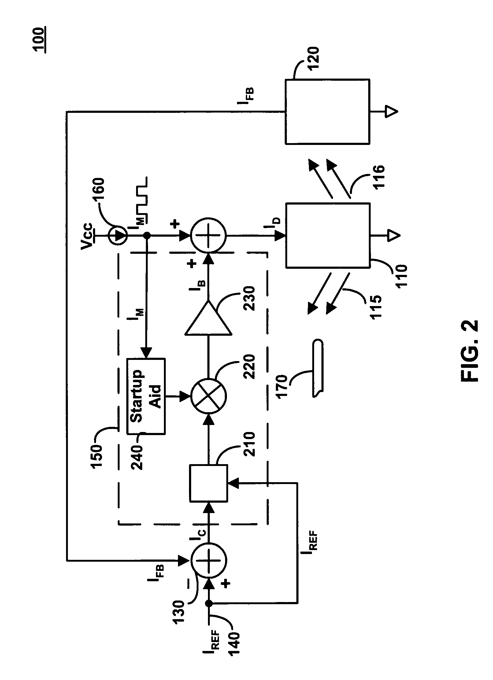
[0033]A gain normalization system 100 constructed in accordance with the principles of the present invention is shown in FIG. 2. As in FIG. 1 gain normalization system 100 includes a lightwave emitter 110, a lightwave detector 120, a summing node 130, a reference signal 140, a modulator circuit 160, and optionally, may be coupled to optical transmission medium 170.

[0034]Lightwave emitter 110 may be any suitable controlled lightwave emitting source such as a laser, a laser diode, a vertical cavity surface emitting laser (VCSEL), an edge emitting laser, a light emitting diode (LED), etc. Lightwave detector 120 may be any detector suitable for detecting light such as a photodiode, a phototransistor, a photoelectric detector, a charge coupled device (CCD), etc.

[0035]Gain normalization system 100 has been improved as compared to the system shown in FIG. 1, however, by replacing fixed gain circuit 20 with variable gain circuit 150. As can be seen, circuit 150 is coupled to modulator 160 a...


PUM


Abstract

Circuits and methods for automatically controlling lightwave emitters are provided. A control system is provided that includes a variable gain circuit for automatically adjusting the gain of a control signal with respect to a feedback signal, a modulation signal, and a reference signal. This allows the optical output of the lightwave emitter to remain substantially constant despite changes in transfer ratio due to aging or temperature variations. Furthermore, in some embodiments, a user may select the overall gain of the system to optimize response time, bandwidth, or steady-state accuracy.

Description

BACKGROUND OF THE INVENTION[0001]This invention relates to automatic power control of light sources. More particularly, this invention relates to gain normalization and automatic power control of modulated light sources.[0002]Recently, there has been a dramatic increase in the number of technologies that are based on the transmission of lightwave signals. Some popular examples of these technologies include data retrieval systems such as DVDs, data transfer systems such as fiber optics, and data acquisition systems such as bar code scanners. Generally speaking, lightwave systems are desirable because they take advantage of the unique properties of light such as extended bandwidth, the ability to propagate long distances with little loss, and resistance to electro-magnetic interference (EMI).[0003]Lightwave technology has revolutionized the transmission of electronic information. For example, fiber optic communications systems that use semiconductor lasers can attain data rates far in...

Claims


Application Information

Patent Timeline
IPC IPC(8): H01S3/13H01S5/042H01S5/068H01S5/0683
CPCH01S5/06832H01S5/0427H01S5/06825
Inventor ROACH, STEVEN D.
Owner ANALOG DEVICES INT UNLTD
Why Eureka
Try Eureka