
Silicon carbide MOSFETs with integrated antiparallel junction barrier Schottky free wheeling diodes and methods of fabricating the same

a technology of silicon carbide mosfet and antiparallel junction barrier, which is applied in the direction of diodes, semiconductor devices, electrical equipment, etc., can solve the problems of limiting the operation of the device, limiting the power mosfet, and pin diodes having a high minority carrier lifetime, and achieves a higher concentration of doping.

Inactive Publication Date: 2005-12-27
CREE INC
View PDF113 Cites 236 Cited by
  • Summary
  • Abstract
  • Description
  • Claims
  • Application Information

AI Technical Summary

Benefits of technology

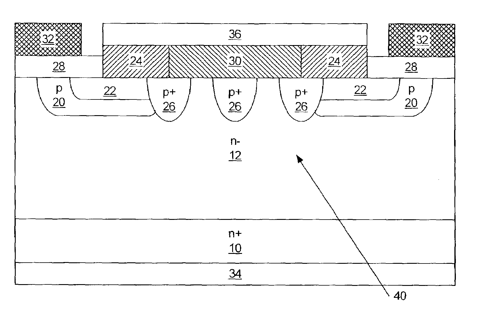
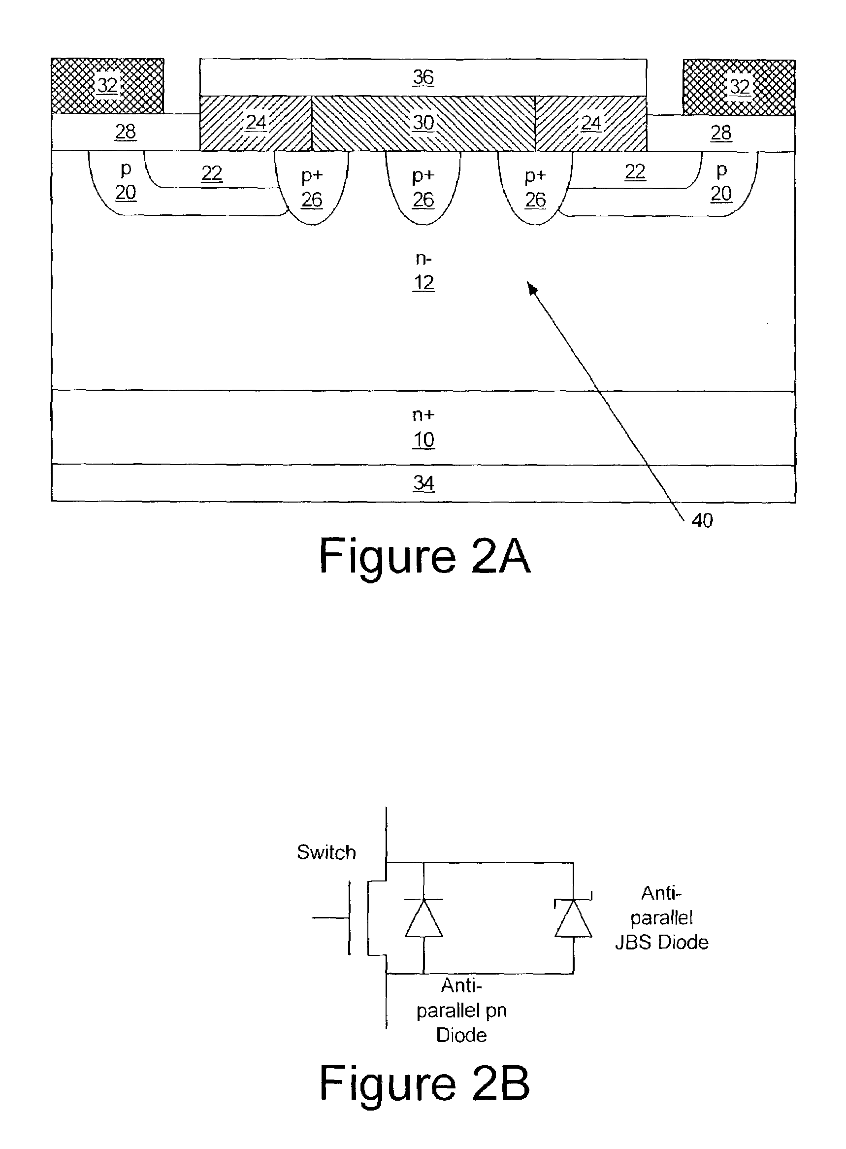
The present invention provides silicon carbide semiconductor devices with a silicon carbide DMOSFET and an integral silicon carbide Schottky diode that have a lower turn-on voltage than a built-in pn junction of the DMOSFET and a p-type well region. The silicon carbide Schottky diode has a turn-on voltage of about 1 volt. The invention also provides methods of fabricating these devices and methods of use. The technical effect of the invention is to provide a more efficient and reliable silicon carbide semiconductor device with improved performance and reliability.

Problems solved by technology

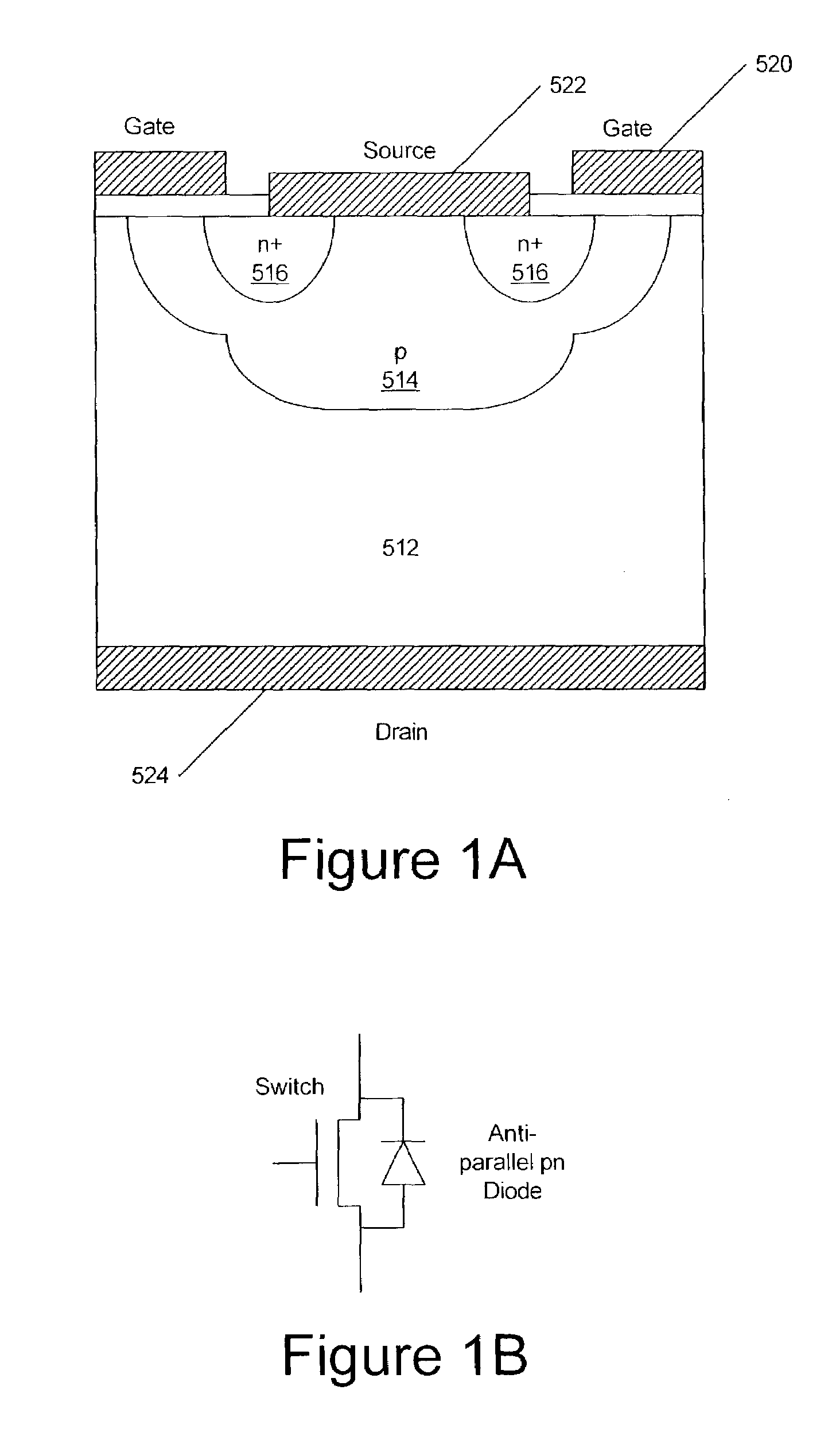
However, in many cases, the switching of the power MOSFET is limited by the speed of the built-in body diode.
However, the built-in body diode may limit operation of the device at high frequencies, for example, frequencies greater than 100 kHz.
A PiN diode has a high minority carrier lifetime and may often fail to keep Up with the switching speed of the MOSFET.
However, external snubber circuits may be expensive and bulky.
However, this method may be ineffective because in the reverse recovery mode the slowest diode provides the dominant current path.
However, this leads to large parasitic output capacitance of the MOSFET-diode pair since a large area diode is needed in parallel configuration.

Method used


Image

  • Silicon carbide MOSFETs with integrated antiparallel junction barrier Schottky free wheeling diodes and methods of fabricating the same
  • Silicon carbide MOSFETs with integrated antiparallel junction barrier Schottky free wheeling diodes and methods of fabricating the same
  • Silicon carbide MOSFETs with integrated antiparallel junction barrier Schottky free wheeling diodes and methods of fabricating the same

Examples


Embodiment Construction

[0028]The present invention now will be described more fully hereinafter with reference to the accompanying drawings, in which preferred embodiments of the invention are shown. This invention may, however, be embodied in many different forms and should not be construed as limited to the embodiments set forth herein; rather, these embodiments are provided so that this disclosure will be thorough and complete, and will fully convey the scope of the invention to those skilled in the art. As illustrated in the Figures, the sizes of layers or regions are exaggerated for illustrative purposes and, thus, are provided to illustrate the general structures of the present invention. Like numbers refer to like elements throughout. It will be understood that when an element such as a layer, region or substrate is referred to as being “on” another element, it can be directly on the other element or intervening elements may also be present. In contrast, when an element is referred to as being “dir...


PUM

PropertyMeasurementUnit
turn-on voltageaaaaaaaaaa
bias voltageaaaaaaaaaa
thicknessaaaaaaaaaa

Abstract

Silicon carbide semiconductor devices and methods of fabricating silicon carbide semiconductor devices have a silicon carbide DMOSFET and an integral silicon carbide Schottky diode configured to at least partially bypass a built in diode of the DMOSFET. The Schottky diode may be a junction barrier Schottky diode and may have a turn-on voltage lower than a turn-on voltage of a built-in body diode of the DMOSFET. The Schottky diode may have an active area less than an active area of the DMOSFET.

Description

FIELD OF THE INVENTION[0001]The present invention relates to semiconductor devices and the fabrication of semiconductor devices and more particularly, to silicon carbide (SiC) metal-oxide semiconductor field effect transistors (MOSFETs) and the fabrication of such MOSFETs.BACKGROUND OF THE INVENTION[0002]Power devices are widely used to carry large currents and support high voltages. Modern power devices are generally fabricated from monocrystalline silicon semiconductor material. One widely used power device is the power Metal Oxide Semiconductor Field Effect Transistor (MOSFET). In a power MOSFET, a control signal is supplied to a gate electrode that is separated from the semiconductor surface by an intervening insulator, which may be, but is not limited to, silicon dioxide. Current conduction occurs via transport of majority carriers, without the presence of minority carrier injection that is used in bipolar transistor operation. Power MOSFETs can provide an excellent safe operat...

Claims


Application Information

Patent Timeline
Patent Type & Authority Patents(United States)
IPC IPC(8): H01L21/04H01L29/24H01L29/78H01L29/872
CPCH01L29/872H01L29/7806H01L29/66068H01L29/0619H01L29/1608
Inventor RYU, SEI-HYUNG
Owner CREE INC
Learn More