
Method and apparatus for rapidly measuring optical transmission characteristics in photonic networks

a photonic network and transmission characteristic technology, applied in the direction of instruments, amplitude demodulation, transmission monitoring, etc., can solve the problems of reducing the time taken to build up the error ratio pattern for an individual channel, affecting the accuracy of the obtained signal, and affecting the quality of the received signal

Inactive Publication Date: 2005-12-27
CIENA
View PDF15 Cites 16 Cited by
  • Summary
  • Abstract
  • Description
  • Claims
  • Application Information

AI Technical Summary

Benefits of technology

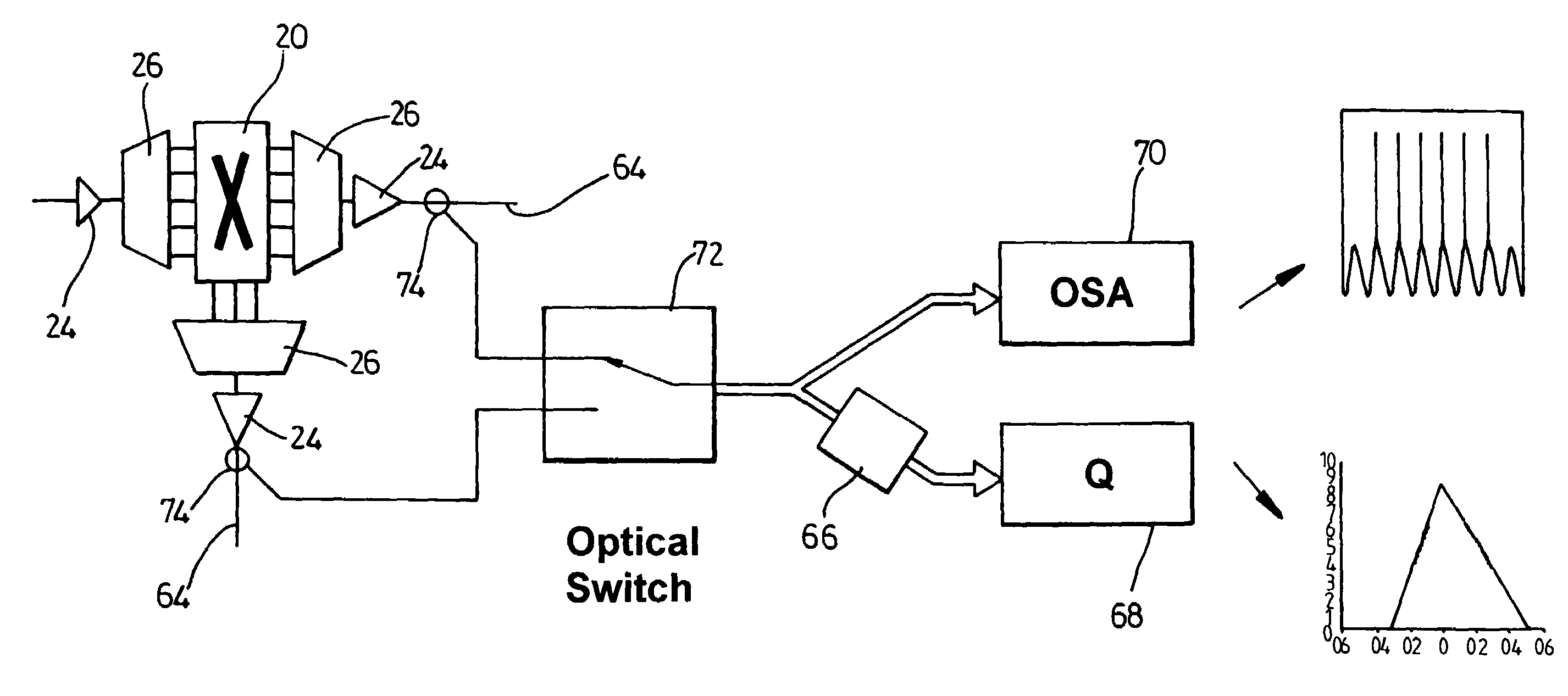
The invention provides an apparatus and method for measuring the error ratio of individual channels in a WDM optical signal. This is useful for detecting and locating faults in optical communication networks. The apparatus includes a wavelength-selective filter for separating the individual channels, a measurement circuit for measuring the error ratio of each channel using a first decision threshold level, and control circuitry for altering the decision threshold level for successive cycles of the measurement circuit. The measurement circuit measures the error ratio by monitoring the channel with the applied decision threshold level for a predetermined time period, and an error warning indicator provides an error warning if the measured error ratio exceeds the expected error ratio for the particular decision threshold level. The invention also provides a network comprising nodes and optical amplifiers between the nodes, wherein each node comprises an optical switching arrangement for performing routing of signals across the network, and each optical amplifier is provided with optical spectrum analysis apparatus for detecting faults. The invention also provides a protocol independent Q-value measurement method and apparatus.

Problems solved by technology

Optical signals suffer degradation between the transmitter and receiver from such factors as noise, inter-symbol interference, fiber dispersion, non-linearity of the elements and transmission medium.
In the last decade, transmission rates of data signals have increased progressively, which has led to more complex and less tolerant transmission systems.
With various types of dispersion shifted fiber, dispersion compensating fiber and dispersion compensating elements that make up a given link, determining the cause of a distortion in the received signal is no longer a simple operation, especially in optical transmission systems with in-line optical amplifiers.
System performance degradation caused by noise and optical path distortions are also usually difficult to separate, making the performance evaluation complicated.
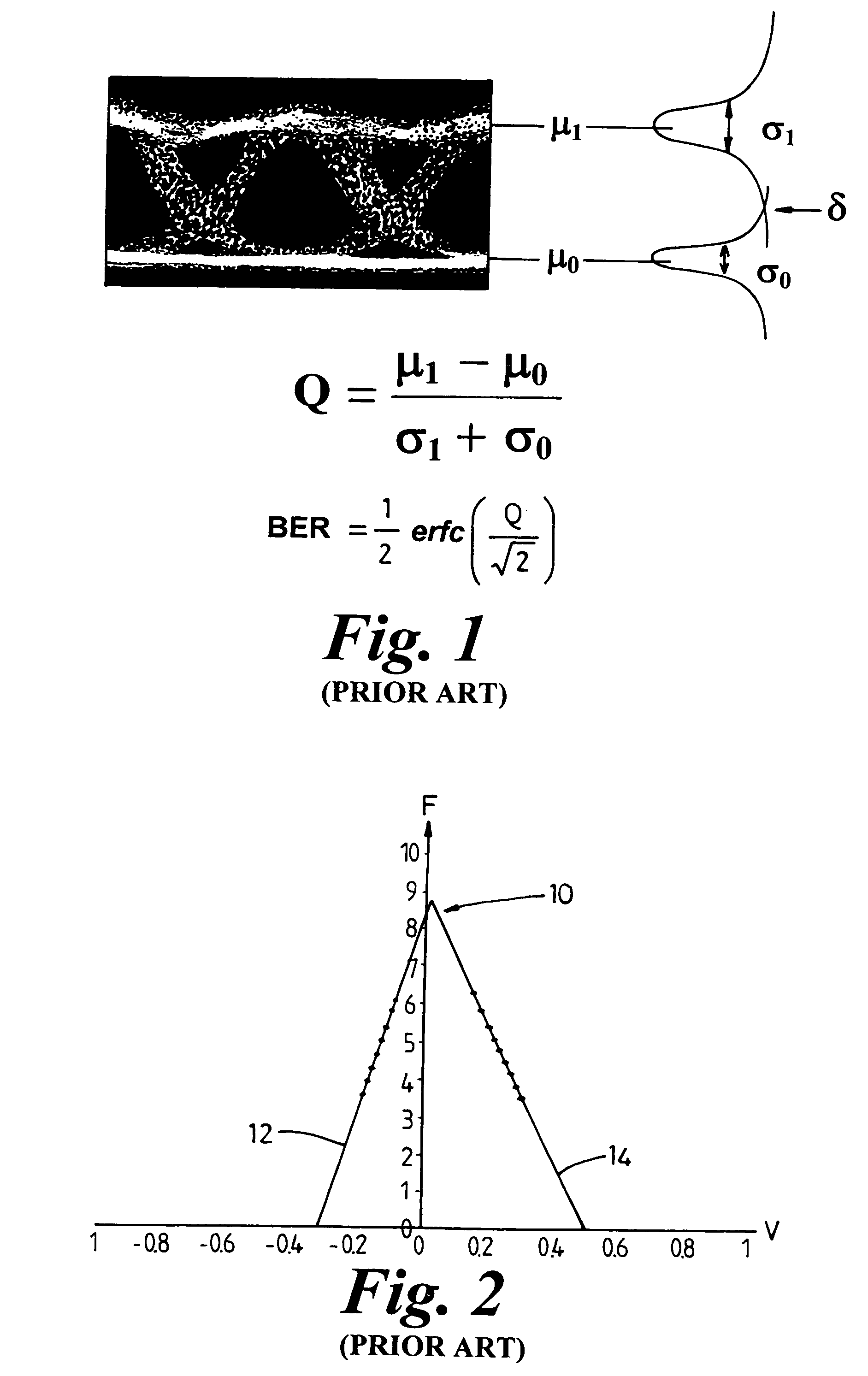
Optical systems have very low BERs under nominal conditions of operation, and therefrom measurement of BER under normal operating conditions is extremely time consuming.
The measurement of the Q value is much quicker, but can still be too slow for some applications.
There will, however be a greatly increased error ratio in interpreting the zeros.
Measuring the Q value for each channel in turn results in an unacceptable delay between successive measurements on an individual channel.
This complicates and increases the cost of the measurement circuitry.

Method used


Image

  • Method and apparatus for rapidly measuring optical transmission characteristics in photonic networks
  • Method and apparatus for rapidly measuring optical transmission characteristics in photonic networks
  • Method and apparatus for rapidly measuring optical transmission characteristics in photonic networks

Examples


Embodiment Construction

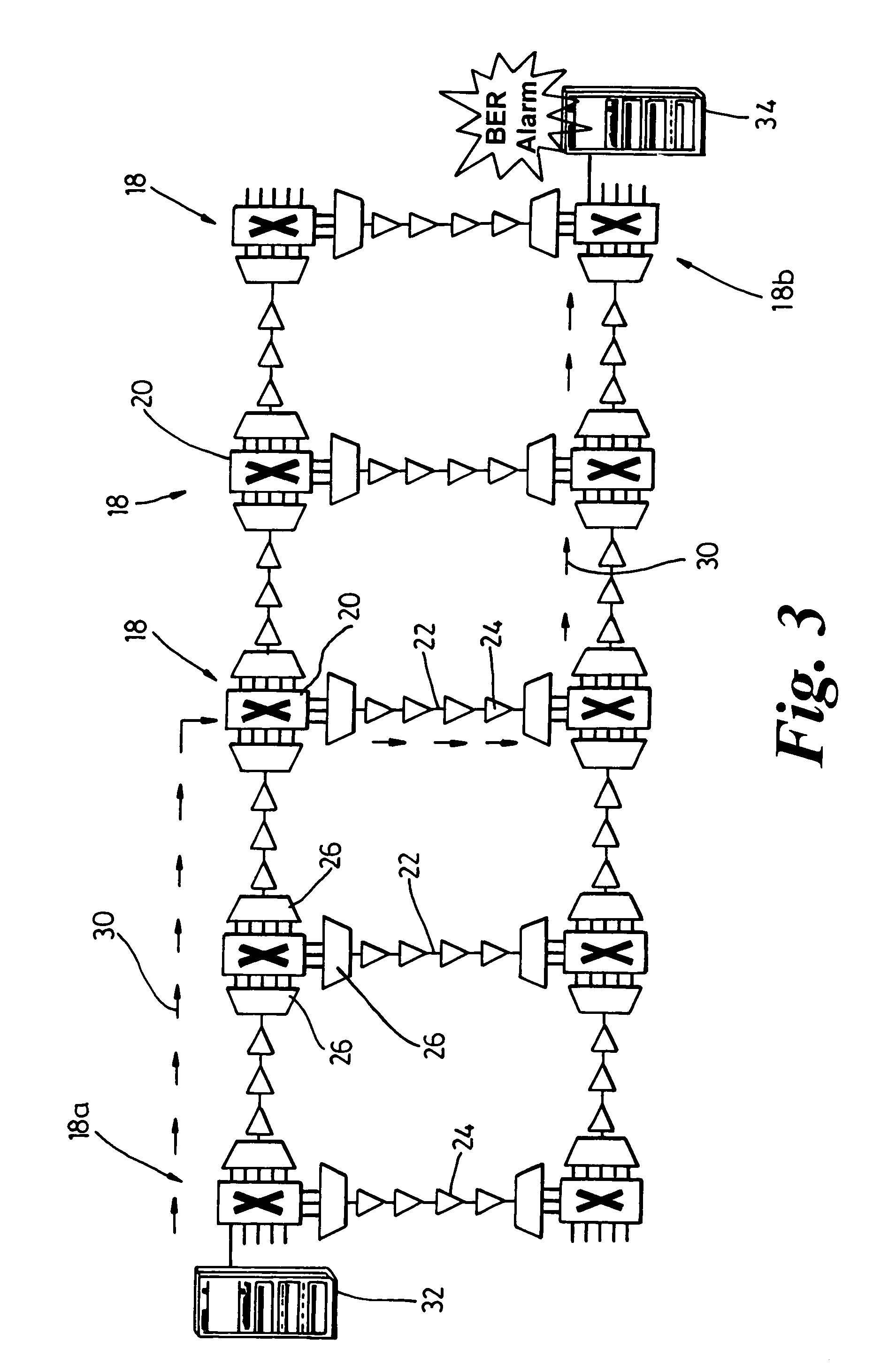
[0042]FIG. 3 shows a WDM optical communications network comprising a plurality of interconnected nodes 18, each node comprising an optical switching arrangement 20 for performing routing of signals across the network. The nodes are connected together by optical fibers 22 along which optical amplifiers 24 are placed. The fibers 22 carry WDM optical signals, and each node comprises a multiplexing / demultiplexing units 26 which provide the individual channels of the WDM system on individual fibers to the switching arrangement 20.

[0043]The arrows 30 indicate one possible connection through the network enabling equipment 32 at a source node 18a to communicate with equipment 34 at a destination node 18b. The equipment 32, 34 is any device which provides optical signals for transmission over the network or which is provided for receiving signals from the network.

[0044]Dense-WDM systems are evolving towards all-optical solutions in which switching and routing take place in the optical domain...


PUM


Abstract

An apparatus for determining an error ratio of individual channels of a WDM optical signal comprises a wavelength-selective filter for separating the individual channels of the WDM signal and a measurement circuit for measuring an error ratio of one channel using a first decision threshold level. The measurement circuit is operable to cycle through all channels, taking an error ratio measurement for each channel in sequence with a predetermined decision threshold level. Control circuitry alters the decision threshold level for successive cycles of the measurement circuit.The apparatus measures error ratio values for each channel in turn, building up an error ratio vs. threshold pattern enabling the Q value to be obtained. Although the time taken to build up the error ratio pattern for an individual channel is not shortened, measurements are taken on each channel at much shorter intervals. This means that signal degradations can be detected much more rapidly, as these signal degradations will be reflected in each error ratio measurements, and do not require a completely updated error ratio pattern to be obtained.

Description

FIELD OF THE INVENTION[0001]This invention relates to performance evaluation analysis in optical systems, and particularly to enable the location of sources of degradations to be located within an optical communications network.BACKGROUND OF THE INVENTION[0002]Optical signals suffer degradation between the transmitter and receiver from such factors as noise, inter-symbol interference, fiber dispersion, non-linearity of the elements and transmission medium. In addition, in amplified wavelength division multiplexed (WDM) systems, the transmission characteristics vary from one channel to another due to the non-flat gain and noise profile of erbium-doped fiber amplifiers (EDFAs).[0003]Distortion is defined as any inaccurate replication of a signal transmitted over a communication link, and could originate in any network element (NE) along the link. It can be measured by assessing the difference between the wave shape of the original signal and that of the signal at the network element o...

Claims


Application Information

Patent Timeline
Patent Type & Authority Patents(United States)
IPC IPC(8): H04B10/02H04B10/08
CPCH04B10/07953
Inventor ANSLOW, PETER JHEATH, RICHARD W
Owner CIENA
Learn More