Burner system and method for mixing a plurality of solid fuels

a burner system and solid fuel technology, applied in the direction of incinerator equipment, combustion types, lighting and heating apparatus, etc., can solve the problems of limited effectiveness of using biomass fuel as a means of reducing nosub>x /sub>emission, ineffective method of cofiring, etc., to enhance the mixing of secondary solid fuel and enhance the effect of secondary solid fuel

Inactive Publication Date: 2006-01-17
FOSTER WHEELER NORTH AMERICA CORP
View PDF35 Cites 14 Cited by
  • Summary
  • Abstract
  • Description
  • Claims
  • Application Information

AI Technical Summary

Benefits of technology

[0015]In one illustrative embodiment, a cofiring burner system comprises a burner assembly including a scroll-type fuel injector. The scroll-type fuel injector includes a primary solid fuel port, or inlet, for receiving a primary solid fuel, a secondary solid fuel port, or inlet, for receiving a secondary solid fuel, an outer barrel and a diffuser element. The primary solid fuel and the secondary solid fuel enter the fuel injector tangentially, although alternatively the secondary fuel can enter the fuel injector axially, and are mixed in the outer barrel. The diffuser element is located in the outer barrel to further enhance the mixing of the secondary solid fuel with the primary solid fuel within the fuel injector before injection into the combustion zone.
[0016]In another embodiment, a cofiring burner system comprises a burner assembly including a elbow-type fuel injector. The elbow-type fuel injector includes a primary solid fuel port, or inlet, for receiving a primary solid fuel, a secondary solid fuel port, or inlet, for receiving a secondary solid fuel, a barrel and an impeller or other spreading device. The primary solid fuel and the secondary solid fuel enter the fuel injector axially and are mixed in the barrel. The impeller is located within a barrel of the fuel injector coupled to the secondary inlet port to further enhance the mixing of the secondary solid fuel with the primary solid fuel within the fuel injector before injection into the combustion zone.

Problems solved by technology

Second, in a flame a biomass fuel releases volatiles at lower temperatures than pulverized coal.
Unfortunately, in pulverized coal fired boilers, limitations have been encountered regarding the effectiveness of using a biomass fuel as a means for reducing NOx emissions.
These limitations result from the technique used to cofire the biomass fuel with the pulverized coal.
However, this method of cofiring is only partially effective and does not provide the most effective means of utilizing the NOx reduction benefits of the volatiles in the biomass fuel.
In particular, since the pulverized coal is injected separately, the volatiles released from the biomass fuel in the core of the flame may not be able to scavenge oxygen and effectively reduce NO formed from the pulverized coal.
However, the level of biomass cofiring is severely limited by this injection technique due to mill performance.
As such, although some NOx reduction benefits may result from the cofiring of a biomass fuel with pulverized coal in wall-fired burners, the existing techniques do not appear to achieve the maximum possible level of NOx reduction.
However, biomass fuels generally have significantly higher oxygen content than pulverized coals and when transported to the burner with air can cause an increase in the stoichiometry in the core of the flame and may increase NOx formation, thus negating the beneficial NOx reduction effects of the high volatile content of the biomass fuel.
In addition, no field experience has been demonstrated to date involving the cofiring of a biomass fuel with pulverized coal in current low NOx burners.
However, predictive computer models of current low NOx burners indicate that NOx may actually increase in a full-scale low NOx burner flame when cofiring, e.g., sawdust and coal.
Thus, current low NOx burner applications do not maximize the beneficial effects of the high volatile content of biomass fuels for NOx reduction, while inhibiting the effects of their high oxygen content on NOx formation.
Petroleum coke, unlike coal, is very low in volatile content which makes it hard to ignite and burn out when fired in boilers not specifically designed for this fuel.
The percentage of petroleum coke that can be fired with the coal is usually limited to about 20 percent by weight, since higher levels will result in flame stability problems due to the low volatile content of the petroleum coke.
This limitation is partially due to the fact that petroleum coke is hard to grind and a sufficiently fine size distribution generally cannot be achieved when it is blended with coal and ground in a mill designed for coal.
Coarse petroleum coke not only results in flame stability problems, but also leads to a high level of unburned carbon (UBC) in the fly ash.
Unfortunately, these coals typically are also hard to grind, thus often limiting the percentage of petroleum coke that can be ground with them in a mill.
However, there is no description in this patent of the structure of the mixer or its affect on the flame stability and UBC issues with respect to petroleum coke.
As such, although petroleum coke can be cofired with coal in wall-fired burners, a method of cofiring petroleum coke has not been developed that provides maximum flame stability and minimal fly ash UBC while maintaining minimum NOx emissions.

Method used


Image

  • Burner system and method for mixing a plurality of solid fuels
  • Burner system and method for mixing a plurality of solid fuels
  • Burner system and method for mixing a plurality of solid fuels

Examples


Embodiment Construction

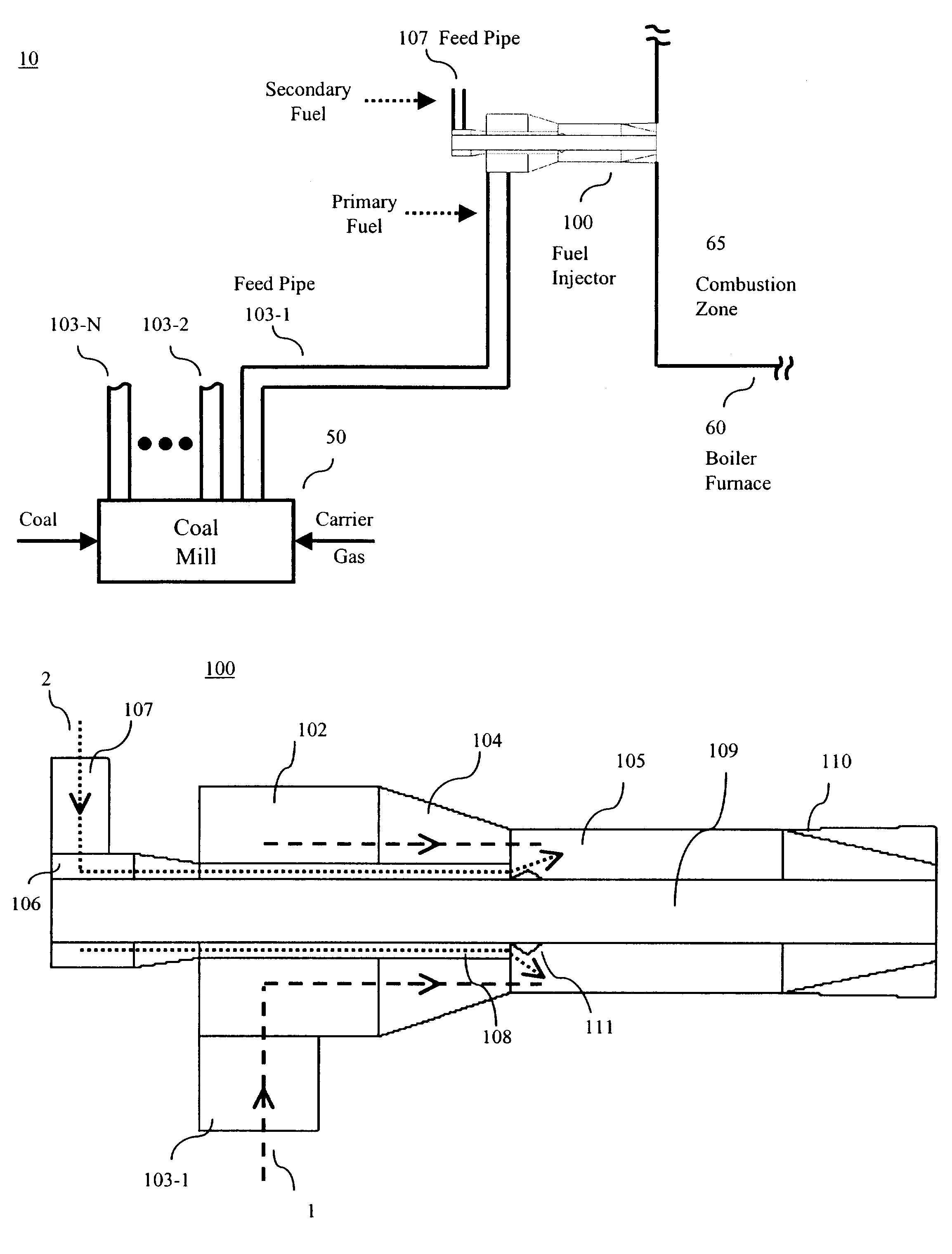
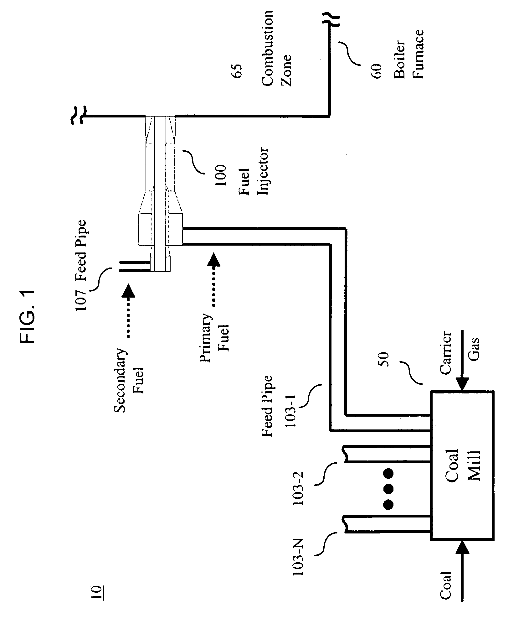
[0025]Other than the inventive concept, the apparatus and methods for a cofiring burner system are well known and are not described further herein. For example, other than the inventive concept, a fuel injector is a portion of the combustion equipment that injects the fuels and carrier gas into a combustion zone. Also, like numbers on different figures represent similar elements.

[0026]An illustrative cofiring burner system in accordance with the principles of the invention is shown in FIG. 1. Cofiring burner system 10 comprises a coal mill (fuel preparation plant) 50, a number of feed pipes, 103-1 to 103-N (primary feed pipes), and 107 (representative of secondary feed pipes), a fuel injector 100 and a boiler furnace, of which a portion 60 is shown (hereafter boiler furnace 60) having a combustion zone 65. Illustratively a primary fuel, e.g., coal, and a transport medium (or carrier gas) (e.g., air) are provided to a fuel preparation plant as represented by coal mill 50, which pulve...


PUM


Abstract

A burner assembly cofires a primary solid fuel and a secondary solid fuel in a combustion zone of a boiler. The burner assembly includes a fuel injector that mixes the primary solid fuel and the secondary solid fuel prior to injection into the combustion zone of the boiler. The primary solid fuel may be pulverized coal, pulverized petroleum coke, or the like, while the secondary solid fuel may be a biomass fuel or refuse-derived fuel.

Description

BACKGROUND OF THE INVENTION[0001]This invention relates generally to solid fuel burner systems and, more particularly, to burner systems that burn or cofire a plurality of types of solid fuels.[0002]One method of cofiring involves the use of a biomass fuel—a renewable source—to provide a low-cost-solution for generating electricity. This method involves cofiring a biomass fuel (e.g., sawdust) as a secondary fuel with pulverized coal (the primary fuel) in a coal-fired boiler. Advantageously, the CO2 emissions from the burning of a biomass fuel is considered to be environmentally benign. In addition, firing biomass fuels results in a reduction in SO2 emissions due to the lower fuel sulfur content compared to coal. Finally, a reduction in NOx emissions may also be achieved due to the lower nitrogen content of the biomass fuel, coupled with beneficial effects of the volatiles of the biomass fuel during the early stages of combustion.[0003]The potential reduction of NOx from the cofiring...

Claims


Application Information

Patent Timeline
Patent Type & Authority Patents(United States)
IPC IPC(8): F23C1/10F23D1/00F23C1/00
CPCF23C1/00F23D1/00F23C2900/99004F23G2900/7013F23G2201/10F23G2209/26
Inventor VATSKY, JOELCONN, RICHARD E.
Owner FOSTER WHEELER NORTH AMERICA CORP
Why Eureka
Try Eureka