Plasma treatment method and apparatus

a technology of plasma sheath and apparatus, applied in the direction of vacuum evaporation coating, electrolysis components, coatings, etc., can solve the problems of reducing productivity, reducing the efficiency of plasma sheath, and reducing the ability of plasma sheath to run at another frequency band, so as to promote the incidence of ions

Inactive Publication Date: 2006-01-31
TOKYO ELECTRON LTD
View PDF36 Cites 22 Cited by
  • Summary
  • Abstract
  • Description
  • Claims
  • Application Information

AI Technical Summary

Benefits of technology

[0009]An object of the present invention is therefore to provide plasma treatment method and apparatus capable of controlling both of the dissociation of gas molecules and the follow-up of ions and also capable of promoting the incidence of ions onto a substrate to be treated.
[0010]Another object of the present invention is to provide plasma treatment method and apparatus capable of raising the plasma density with smaller high frequency power not to damage the substrate to be treated.
[0013]High frequency power having the frequency lower than the lower limit of ion transit frequencies is applied to the lower electrode. Therefore, the follow-up of ions becomes more excellent and ions can be more efficiently accelerated with a smaller power. In addition, both of ion and electron currents change more smoothly. Further, the follow-up of ions does not depend upon kinds of ion. The plasma treatment can be thus made more stable even when the degree in the process chamber and the rate of gases mixed change. On the other hand, high frequency power having the frequency higher than the upper limit of ion transit frequencies is applied to the upper electrode. Therefore, ions can be left free from frequencies of their transit frequency zone to thereby enable more stable plasma to be generated.
[0015]Impedances including such capacitive components that the impedance relative to high frequency power becomes smaller than several kΩ and that the impedance relative to relatively low frequency power becomes larger than several Ω are arranged in series between the upper electrode and its matching circuit and between them and the ground. Current is thus made easier to flow to raise the plasma density and ion control.

Problems solved by technology

However, ions (loaded particles) easily run from plasma to the wafer at a frequency band, but it becomes difficult for them to run from the plasma sheath to the wafer at another frequency band (or transit frequency zone).
Plasma properties such as ion current density become thus unstable and the plasma treatment becomes uneven, thereby causing the productivity to be lowered.

Method used


Image

  • Plasma treatment method and apparatus
  • Plasma treatment method and apparatus
  • Plasma treatment method and apparatus

Examples


first embodiment

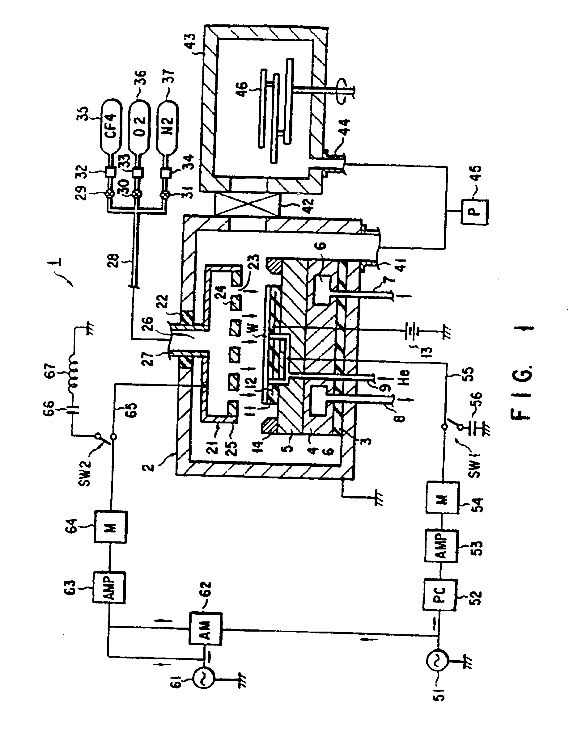
[0061]Some embodiments of the present invention will be described with reference to the accompanying drawings. Referring to FIGS. 1 through 5, a first embodiment will be described.

[0062]A process chamber 2 of an etching treatment apparatus 1 is assembled by alumite-processed aluminium plates. It is earthed and a suscepter 5 insulated by an insulating plate 3 is arranged in it. The suscepter is supported by its bottom through the insulating plate 3 and a support 4.

[0063]A coolant chamber 6 is formed in the suscepter support 4. It is communicated with a coolant supply supply (not shown) through inlet and outlet pipes 7 and 8 and coolant such as liquid nitrogen is circulated between it and the coolant supply supply.

[0064]An internal passage 9 is formed in a suscepter assembly which comprises the insulating plate 3, the support 4, the suscepter 5 and an electrostatic chuck 11, and heat exchanger gas such as helium gas is supplied from a gas supply supply (not shown) to the underside of ...

second embodiment

[0107]A high frequency power circuit of this apparatus 200 is different from that of the second embodiment in the following points: A suscepter 205 of the apparatus 200 is not earthed; no low pass filter is arranged on the secondary circuit of a transformer 275; and a second transformer 282 is arranged on the circuit of a second power supply 281.

[0108]The second power supply 281 serves to generate high frequency power of 3 MHz. It is connected to the primary side of the transformer 282, whose secondary side are connected to upper and lower electrodes 21 and 205. A controller 293 which controls the distribution of power is also attached to the secondary side of the transformer 282.

[0109]It will be described how the etching treatment is carried out by the apparatus 200.

[0110]High frequency powers of 3 MHz whose phases are shifted from each other by 180° are applied from the power supply 281 to the suscepter 205 and the upper electrode 21 to generate plasma between them. At the same ti...

fourth embodiment

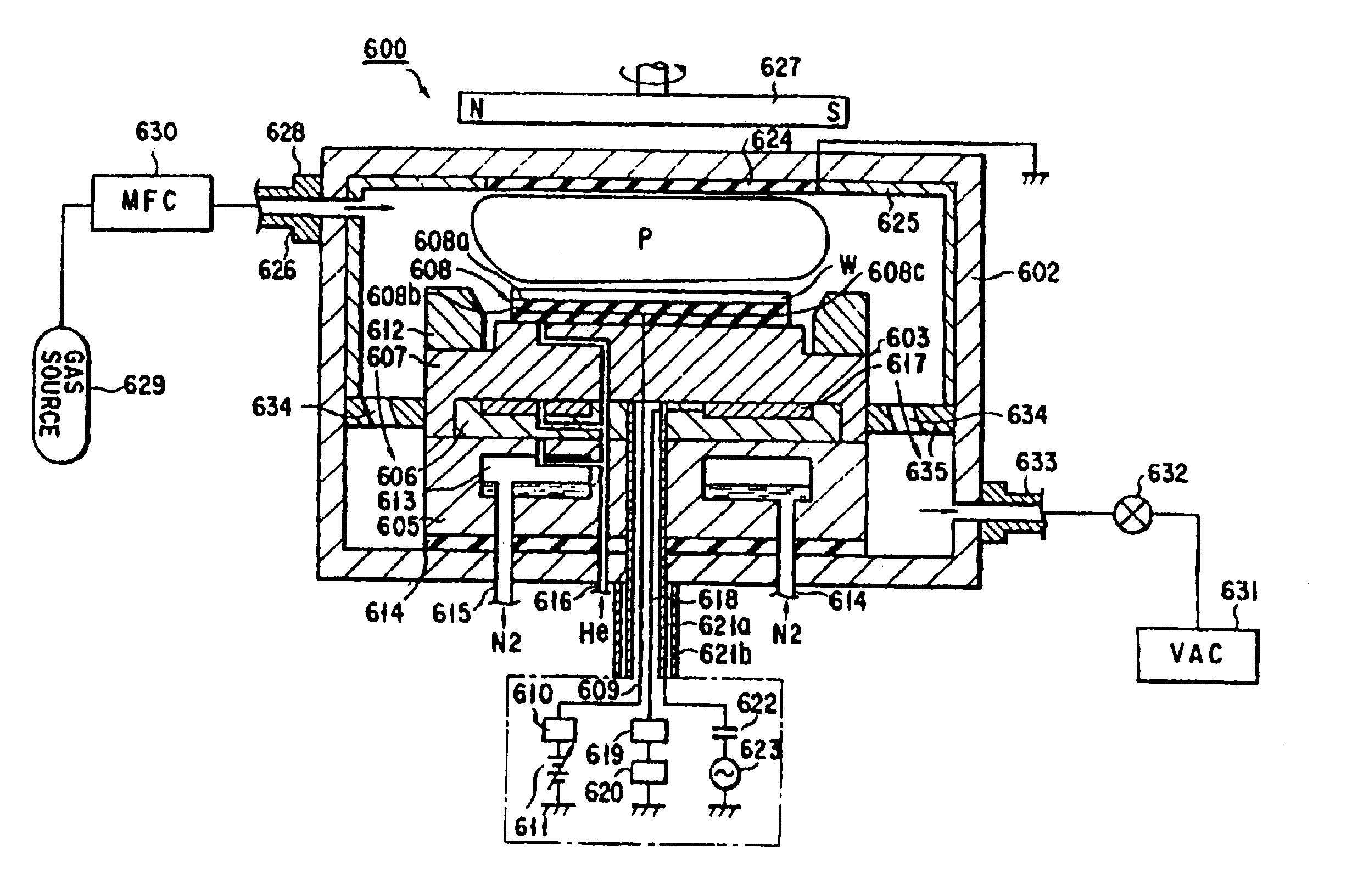
[0113]A fourth embodiment will be described, referring to FIGS. 8 through 12. Same components as those in the above-described embodiments will be mentioned only when needed.

[0114]As shown in FIG. 8, an etching apparatus 300 has a cylindrical or rectangular column-like air-tight chamber 302. A top lid 303 is connected to the side wall of the process chamber 302 by hinges 304. Temperature adjuster means such as a heater 306 is arranged in a suscepter 305 to adjust the treated face of a treated substrate W to a desired temperature. The heater 306 is made, for example, by inserting a conductive resistance heating unit such as tungsten into an insulating sintered body made of aluminium nitride. Current is supplied to this resistant heating unit through a filter 310 to control the temperature of the wafer W in such a way that the treated face of the wafer W is raised to a predetermined temperature.

[0115]A high frequency power supply 319 is connected to the suscepter 305 through a blocking...


PUM

PropertyMeasurementUnit
frequency f2aaaaaaaaaa
voltageaaaaaaaaaa

Abstract

A plasma treatment method comprising exhausting a process chamber so as to decompress the process chamber, mounting a wafer on a suscepter, supplying a process gas to the wafer through a shower electrode, applying high frequency power, which has a first frequency f1 lower than an inherent lower ion transit frequencies of the process gas, to the suscepter, and applying high frequency power, which has a second frequency f2 higher than an inherent upper ion transit frequencies of the process gas, whereby a plasma is generated in the process chamber and activated species influence the wafer.

Description

RELATED APPLICATION[0001]This application is a continuation of Ser. No. 10 / 079,600 filed Feb. 19, 2002 now U.S. Pat. No. 6,544,380 which is a continuation of Ser. No. 09 / 864,022 filed May 23, 2001, now U.S. Pat. No. 6,379,756 issued Apr. 30, 2002, which is a divisional application of Ser. No. 09 / 556,133, filed Apr. 20, 2000, now U.S. Pat. No. 6,264,788 issued Jul. 24, 2001, which is a divisional application of Ser. No. 09 / 094,451, filed Jun. 10, 1998, now U.S. Pat. No. 6,106,737 issued Aug. 22, 2000, which is a divisional application of application Ser. No. 08 / 424,127, filed Apr. 19, 1995, now U.S. Pat. No. 5,900,103 issued May 4, 1999.BACKGROUND OF THE INVENTION[0002]1. Field of the Invention[0003]The present invention relates to a plasma treatment method by which substrates such as semiconductor wafers are etched or sputtered under plasma atmosphere. It also relates to a plasma treatment apparatus for the same.[0004]2. Description of the Related Art[0005]Recently, semiconductor de...

Claims


Application Information

Patent Timeline
Patent Type & Authority Patents(United States)
IPC IPC(8): H01L21/00C23C16/00C23C16/44C23C16/448C23C16/455C23C16/509C23C16/517H01J37/32
CPCC23C16/4405C23C16/4483C23C16/4485C23C16/45565C23C16/4557C23C16/5096C23C16/517H01J37/32082H01J37/32146H01J37/32155H01J37/32165H01J37/3244H01J37/32935H01J37/32963C23C16/4407Y10S156/916H01L21/306
Inventor TAKENAKA, HIROTONISHIKAWA, HIROSHI
Owner TOKYO ELECTRON LTD
Why Eureka
Try Eureka