Eureka AIR delivers breakthrough ideas for toughest innovation challenges, trusted by R&D personnel around the world.

Electronic spinning apparatus

Inactive Publication Date: 2006-01-31
FINETEX TECH GLOBAL +2
View PDF7 Cites 33 Cited by
  • Summary
  • Abstract
  • Description
  • Claims
  • Application Information

AI Technical Summary

Benefits of technology

[0012]It is therefore, an object of the present invention to provide an electronic spinning apparatus which can mass-produce nano fibers by enhancing fiber formation effects by maximizing an electric force supplied to a nozzle block in electronic spinning, namely maintaining the electric force higher than the interface or surface tension of a spinning dope.
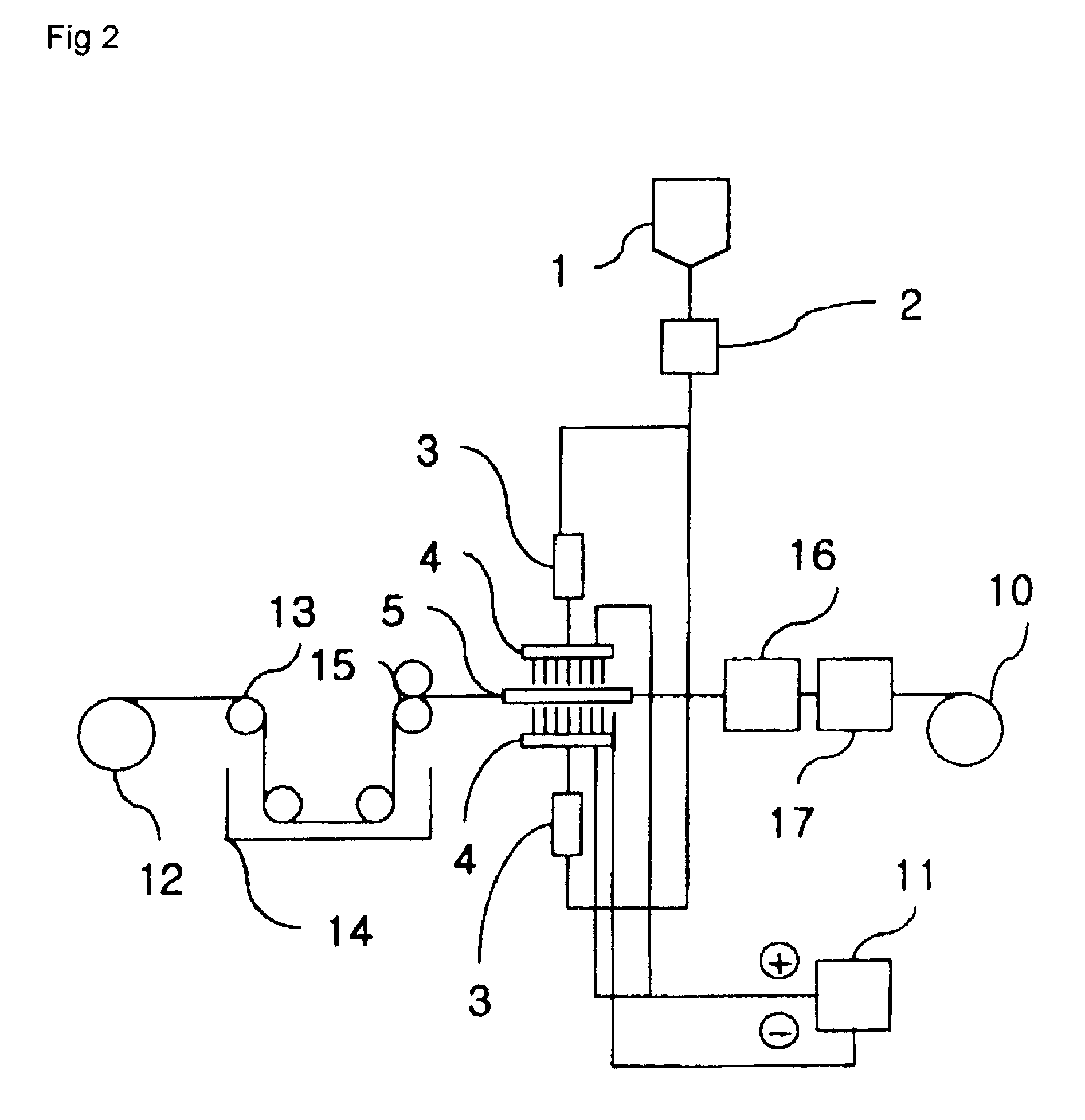
[0042]In accordance with the present invention, when the spinning dope is supplied o the nozzle block 4, flowing of the spinning dope is dropped at least once by using the spinning dope drop device 3, thereby maximizing fiber formation. As a result, fiber formation effects by the electric force are improved to mass-produce the nano and nonOwoven fabrics. Moreover, since the nozzles having the plurality of pins are aligned in block units, the width and thickness of the non-woven fabric can be easily controlled.
[0046]For example, a mask coated with the nano fibers is useful as an anti-bacteria mask, and a spun yarn or filament coated with the nano fibers is useful as a yarn for artificial suede and leather. In addition, coating nylon 6 nano fibers on a paper filter extends the life span of the filter. The fiber material coated with the nano fibers is soft to the touch.

Problems solved by technology

However, the conventional electrospinning apparatus and process for preparing the non-woven fabric using the same have a disadvantage in that an effect of electric force is reduced because the spinning dope is consecutively supplied to the nozzles having the high voltage.
In more detail, the electric force transmitted to the nozzles is dispersed to the whole spinning dope, and thus fails to overcome interface or surface tension of the spinning dopes.
As a result, fiber formation effects by the electric force are deteriorated, which hardly achieves mass production of the fiber.
It is thus difficult to control the width and thickness of the non-woven fabric.

Method used


Image

  • Electronic spinning apparatus
  • Electronic spinning apparatus
  • Electronic spinning apparatus

Examples


example 1

[0071]Nylon 6 chip having relative viscosity of 2.3 was dissolved in formic acid by 20% in 96% of sulfuric acid solution, to prepare a spinning dope. The spinning dope was stored in the main tank 1, quantitatively measured by the metering pump 2, and supplied to the spinning dope drop device 3 of FIG. 2, thereby discontinuously changing flowing of the spinning dope. Thereafter, the spinning dope was supplied to the nozzle block 4 having a voltage of 50 kV, and spun in a fiber shape through the nozzles. The spun fibers were collected on the collector 6, to prepare a non-woven fabric web having a width of 60 cm and weight of 3.0 g / m2. Here, each nozzle block included 200 pins, and 200 nozzle blocks were aligned. Model CH 50 of Symco Corporation was used as the voltage generator. The output rate per one pin was 0.0027 g / min (discharge amount of one nozzle block: 0.54 g / min), and thus a throughput was 108 g / min. One nozzle block was divided into 10, and one spinning dope drop device 3 w...

example 2

[0072]Poly(L-lactide) having a viscosity average molecular weight of 450,000 was dissolved in methylene chloride, to prepare a spinning dope. The spinning dope was stored in the main tank 1, quantitatively measured by the metering pump 2, and supplied to the spinning dope drop device 3 of FIG. 2, thereby discontinuously changing flowing of the spinning dope. Thereafter, the spinning dope was supplied to the nozzle block 4 having a voltage of 50 kV, and spun in a fiber shape through the nozzles. The spun fibers were collected on the collector 6, to prepare a non-woven fabric web having a width of 60 cm and weight of 6.9 g / m2. Here, each nozzle block included 400 pins, and 20 nozzle blocks were aligned. Model CH 50 of Symco Corporation was used as the voltage generator. The output rate per one pin was 0.0026 g / min, and thus a throughput was 20.8 g / min. One nozzle block was divided into 10, and one spinning dope drop device 3 was installed in every 40 pins. A drop speed had 3.2-second ...

example 3

[0073]Poly(glycolide-lactide) copolymer (mole ratio: 50 / 50) having a viscosity average molecular weight of 450,000 was dissolved in methylene chloride, to prepare a spinning dope. The spinning dope was stored in the main tank 1, quantitatively measured by the metering pump 2, and supplied to the spinning dope drop device 3 of FIG. 2, thereby discontinuously changing flowing of the spinning dope. Thereafter, the spinning dope was supplied to the nozzle block 4 having a voltage of 50 kV, and spun in a fiber shape through the nozzles. The spun fibers were collected on the collector 6, to prepare a non-woven fabric web having a width of 60 cm and weight of 8.53 g / m2. Here, each nozzle block included 400 pins, and 20 nozzle blocks were aligned. Model CH50 of Symco Corporation was used as the voltage generator. The throughput per one pin was 0.0032 g / min (output rate per one nozzle block: 1.28 g / min), and thus a total output rate was 25.6 g / min. One nozzle block was divided into 10, and o...


PUM

PropertyMeasurementUnit
Linear densityaaaaaaaaaa

Abstract

An electrospinning apparatus including a spinning dope main tank, a metering pump, a nozzle block, a collector positioned at the lower end of the nozzle block for collecting spun fibers, a voltage generator, a plurality of units for transmitting a voltage generated by the voltage generator to the nozzle block and the collector, said electrospinning apparatus containinga spinning dope drop device positioned between the metering pump and the nozzle block, the spinning dope drove device having(i) a sealed cylindrical shape,(ii) a spinning dope inducing tube and a gas inletting tube for receiving gas through its lower end and having its gas inletting part connected to a filter aligned side-by-side at the upper portion of the spinning dope drop device,(iii) a spinning dope discharge tube extending from the lower portion of the spinning dope drop device and(iv) a hollow unit for dropping the spinning dope from the spinning dope inducing tube formed at the middle portion of the spinning dope drop device.

Description

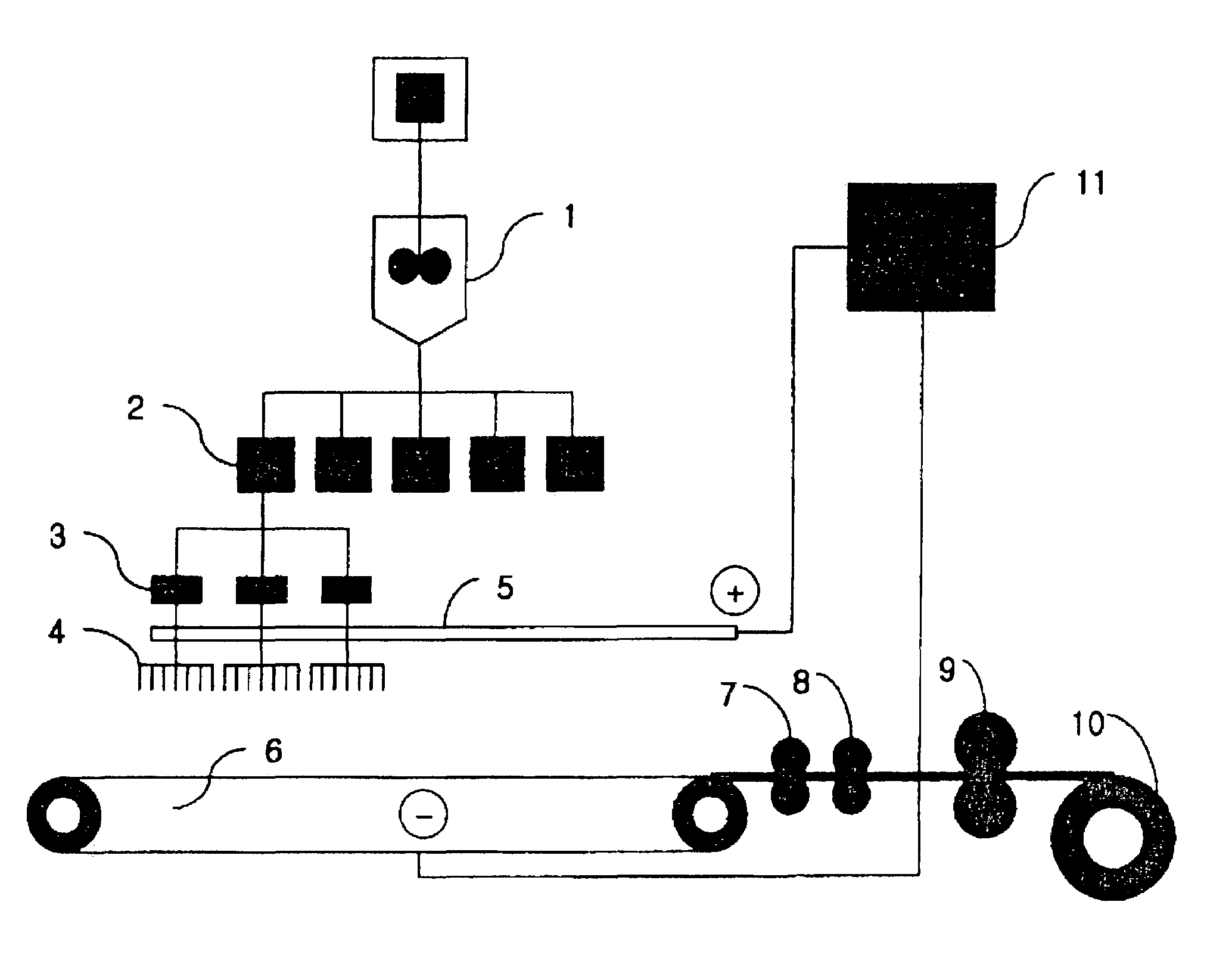
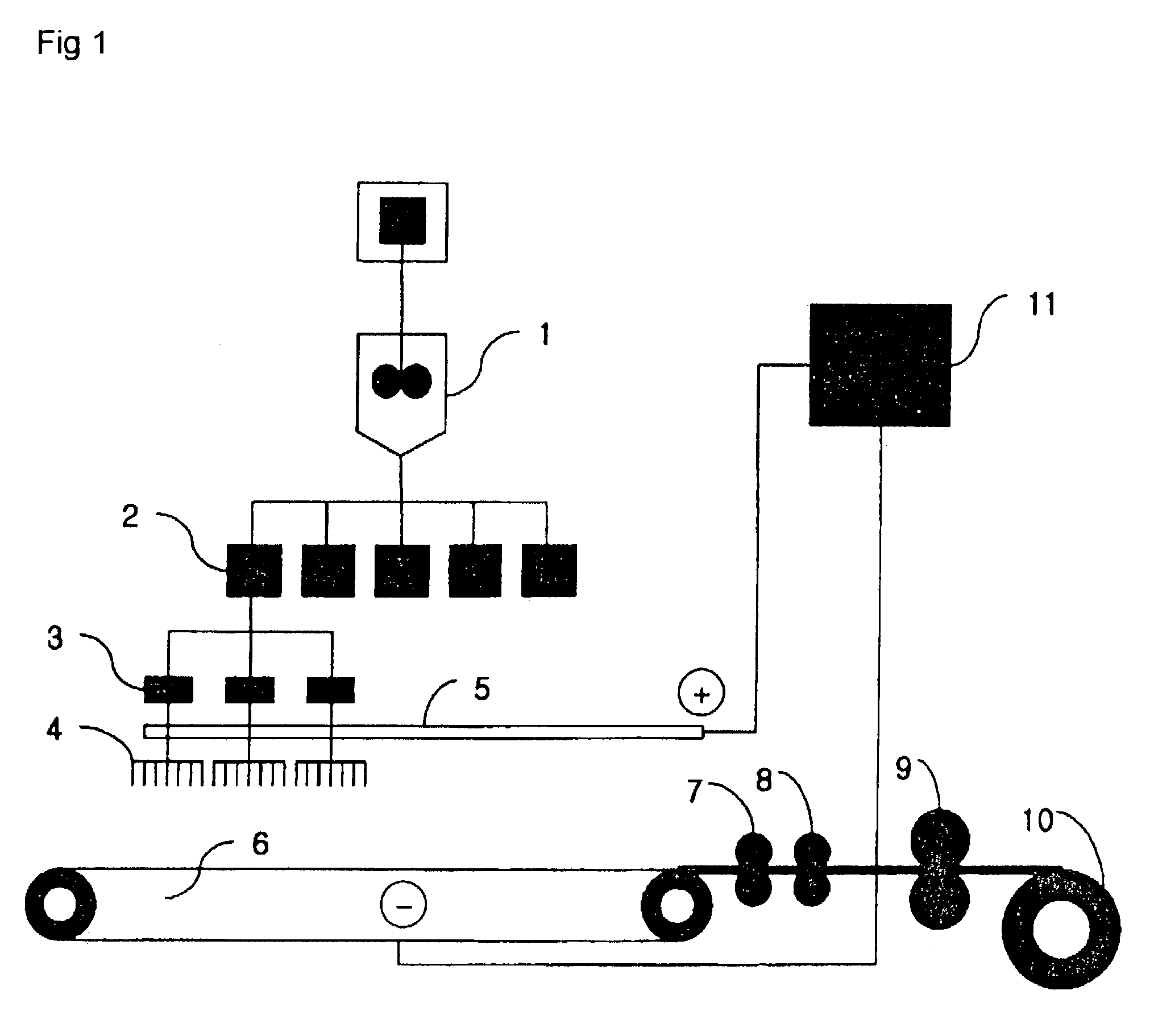
[0001]This application is the national phase under 35 U.S.C. § 371 of PCT International Application No. PCT / KR01 / 02158 which has an International filing date of Dec. 13, 2001, which designated the United States of America.BACKGROUND OF THE INVENTION[0002]1. Field of the Invention[0003]The present invention relates to an electronic spinning (electrospinning) apparatus for mass-producing nano fibers, and a process for preparing a non-woven fabric using the same.[0004]2. Description of the Related Art[0005]A conventional electrospinning apparatus and a process for preparing a non-woven fabric using the same have been disclosed under U.S. Pat. No. 4,044,404. As shown in FIG. 1, the conventional electrospinning apparatus of the patent '404 includes; a spinning dope main tank 1 for storing a spinning dope; a metering pump 2 for quantitatively supplying the spinning dope; a plurality of nozzles for discharging the spinning dope; a collector 6 positioned at the lower end of the nozzles, for...

Claims


Application Information

Patent Timeline
IPC IPC(8): D01D5/00D01D5/06
CPCD01D1/06D01D5/0084D01D5/0069
Inventor KIM, HAG-YONG
Owner FINETEX TECH GLOBAL
Why Eureka
Eureka Blog
Learn More