Method for allocating spare cells in auto-place-route blocks

a technology of auto-placement and routing blocks, which is applied in the direction of cad circuit design, program control, instruments, etc., can solve the problems of individual dies not being functional, the percentage of dies in the array will be non-functional, and the cost of integrated circuits is the yield, so as to reduce the cost, reduce the final die size, and increase the yield

a technology of auto-placement and routing blocks, which is applied in the direction of cad circuit design, program control, instruments, etc., can solve the problems of individual dies not being functional, the percentage of dies in the array will be non-functional, and the cost of integrated circuits is the yield, so as to reduce the cost, reduce the final die size, and increase the yield

US6993738B2Active Publication Date: 2006-01-31IP FIRST

Image

  • Method for allocating spare cells in auto-place-route blocks
  • Method for allocating spare cells in auto-place-route blocks
  • Method for allocating spare cells in auto-place-route blocks

Examples


first embodiment

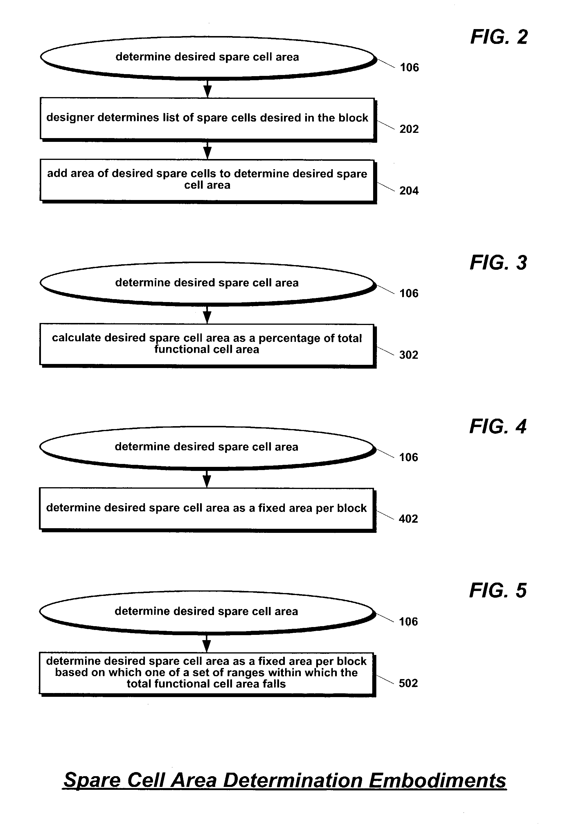
[0041]Referring now to FIG. 2, a flowchart illustrating the step of determining the desired spare cell area of step 106 of FIG. 1 is shown. Flow begins at step 202.

[0042]At step 202, the designer determines the list of spare cells desired to be included in the APR block. Typically, the designer selects types and quantities of the spare cells based on the function of the APR block. Large numbers of logic gates, for example, are commonly included in the spare cell list. Flow proceeds to step 204.

[0043]At step 204, the designer adds the areas of the individual spare cells in the spare cell list determined at step 202 to determine the desired spare cell area of step 106. Flow ends at step 204.

second embodiment

[0044]Referring now to FIG. 3, a flowchart illustrating the step of determining the desired spare cell area of step 106 of FIG. 1 is shown. Flow begins at step 302.

[0045]At step 302, the designer calculates the desired spare cell area for step 106 as a percentage of the total functional cell area determined at step 104 of FIG. 1. For example, the designer might calculate the desired spare cell area as 10% of the total functional cell area. The percentage may vary as a function of the complexity and / or size of the APR block. Flow ends at step 302.

third embodiment

[0046]Referring now to FIG. 4, a flowchart illustrating the step of determining the desired spare cell area of step 106 of FIG. 1 is shown. Flow begins at step 402.

[0047]At step 402, the designer calculates the desired spare cell area for step 106 as a fixed area used as the spare cell area for all blocks in the integrated circuit design. For example, the design might fix the desired spare cell area at 500 square microns. Flow ends at step 402.


PUM


Abstract

A method for placing spare cells into an auto-place-route (APR) block of an integrated circuit is disclosed. The list of functional cells to be included in the block is determined along with the netlist. The sum of the areas of the functional cells and the desired spare cell area is used as the area of the block boundary. The boundary is provided as input to an auto-placement tool along with the netlist and the list of functional cells. The list of functional cells specifically does not include the spare cells so that the tool does not place spare cells in the boundary. Consequently, the spare cell area may be utilized as wiggle-room by the tool to efficiently place the functional cells. The tool produces a placement of the functional cells that includes white space in the boundary. Spare cells are then placed into the white space.

Description

PRIORITY INFORMATION[0001]This application claims priority based on U.S. Provisional Application, Ser. No. 60 / 390,026, filed Jun. 18, 2002, entitled SPARE CELL ALLOCATION METHOD FOR AUTO-PLACE-ROUTE BLOCKS.FIELD OF THE INVENTION[0002]This invention relates in general to the field of methods for automatically placing and routing circuit cells in integrated circuits, and particularly to the allocation of space within the integrated circuits for spare cells.BACKGROUND OF THE INVENTION[0003]In order to more fully appreciate the invention disclosed herein, it is useful to first explain four concepts relevant to integrated circuit design: the relationship of functional block size to yield, the hierarchical nature of integrated circuit design, the use of auto-place-route (APR) tools, and the use of spare cells to make engineering changes (ECs) to integrated circuit designs.[0004]There exists constant market pressure to reduce the cost of integrated circuits. One large factor in the cost of...

Claims


Application Information

Patent Timeline
31 Jan 2006
Publication
US6993738B2
IPC
G06F17/50; G06F9/45; H01L27/02; H01L27/18
CPC
G06F17/5068; H01L27/18; H01L27/0203; G06F30/39; H10N69/00
Inventors
BRAZELL, MARK; ESSBAUM, ALEXANDER