Method and apparatus for facilitating urological procedures

a urological and urological technology, applied in the field of medical science, can solve the problems of urethral obstruction, substantial burden on the delivery of effective care through the healthcare system, and high cost for the healthcare system, hospitals, clinics and doctors' offices

Inactive Publication Date: 2006-02-07
PERCUVISION
View PDF3 Cites 65 Cited by
  • Summary
  • Abstract
  • Description
  • Claims
  • Application Information

AI Technical Summary

Benefits of technology

[0052]Typical methods of using the instrument in accordance

Problems solved by technology

While most placements proceed without problems, typically about ten percent of urinary catheter placements are difficult, causing a substantial burden on the delivery of effective care through the healthcare system.
The most common problem is tetany, a spasm of the external urinary sphincter or stricture of the urethra.
Stones, and even clots descending from the bladder, also constitute urethral obstructions.
The cost to the healthcare system, hospitals, clinics and doctors' offices is substantial.
In addition, the delay in servicing urological catheter patients in a timely manner constitutes poor medical efficiency, delivery and control.
When difficulty is encountered, the resulting frustration among healthcare professionals, especially nurses, physician extenders and physician assistants, creates a very real feeling of ineffectiveness on the part of these healthcare workers, to say nothing of the dissatisfaction on the part of the patients caused by the delay and added discomfort.
While the dollar cost to the healthcare system is not the only concern, such elements as added labor and material costs, time delays for patient rectification, excess space and equipment required, catheter kit value, nurse technician and physician costs constitute an expense to the healthcare system of surprising proportions.
Of these, about 15,000 are difficult.
Moreover, the additional space and equipment amounts to at least $800 million per year for a to

Method used


Image

  • Method and apparatus for facilitating urological procedures
  • Method and apparatus for facilitating urological procedures
  • Method and apparatus for facilitating urological procedures

Examples


example 1

[0053]The use of the instrument in accordance with the present invention will be described in carrying out a transurethral resection of a bladder tumor. This procedure is usually performed under a general or spinal anesthetic because of the discomfort / pain from passage of the instrument and also from that which might occur from the resection of the tumor by electrical current. However, if one is using laser energy (neodinium YAG or Holmium lasers, for example), the patient's intraoperative discomfort / pain is usually less as these procedures can, in that case, be performed without general or spinal anesthesia.

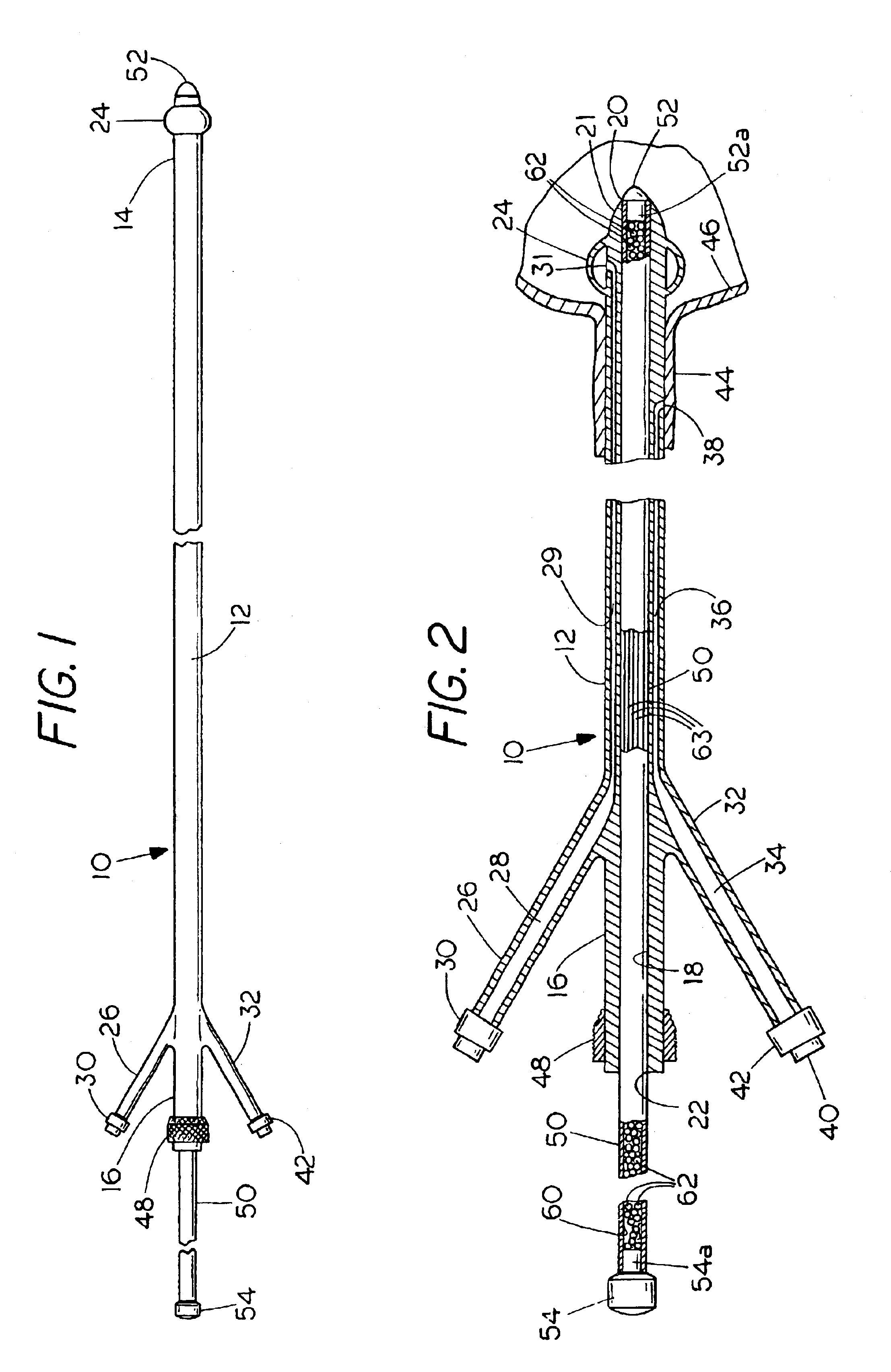
[0054]First, the working sheath 10 is inserted through the urethra as shown in FIG. 2. The obturator 50 is then removed. Generally, a rigid cystoscope (usually 20-23 French) is passed through the lumen 18 of the sheath 10 with a rigid optical lens to evaluate the urethra and bladder to determine the number of tumors, their locations, extent of involvement of the bladder, and pos...

example 2

[0058]The invention will now be described in conducting a laparoscopic pelvic reconstruction procedure, e.g., culpo-suspension, paravaginal repairs, and enterocele repairs.

[0059]First, the working sheath 10 is inserted as shown in FIG. 2. The obturator 50 is then removed. A Foley catheter is then passed through the lumen 18 of the sheath 10 to keep the bladder empty, or the sheath 10 itself can be used for this purpose without a Foley. When the procedure is performed laparoscopically through the working sheath 10, it is frequently necessary to perform a cystoscopic evaluation with the examination of the bladder by passing urethral catheters through the lumen 18 (performed cystoscopically) during or at the end of the laparoscopic procedure. The Foley catheter is removed and the cystoscope is introduced next through the lumen 18 of the sheath 10.

[0060]If it is necessary to perform the evaluation during the laparoscopic procedure, it is necessary that the surgeon carry out the procedur...

example 3

[0062]The invention will be described in removing kidney stones, Nephrolithiasis (renal and ureteral calculi) are quite common urologic problems, requiring emergent surgical intervention. When renal or ureteral calculi are causing blockage of the upper urinary tracts, patients will most commonly experience severe and disabling colicky pain requiring immediate emergency medical attention, including pain management and surgical intervention. No population is immune from the renal colic attack as a result of kidney stones (and as will be discussed later), especially astronauts who are at even greater risk. When these attacks occur, patients are initially evaluated in the emergency room. Once the diagnosis of nephrolithiasis is made, they are admitted to the hospital for management and probable surgical intervention if it is unlikely they will pass the stone on their own or if pain management is a problem.

[0063]First, the working sheath 10 is introduced into the bladder as shown in FIG....


PUM


Abstract

A flexible direct vision fiberoptical viewing cable is placed within a urinary catheter with its tip located at a distal end of the catheter such that the surfaces of the distal end of both the viewing cable and the catheter are aligned so as to fit together in such a way as to form a composite smoothly curved surface to facilitate negotiating obstructions. The cable is maintained in this position within the catheter with the surfaces that comprise the tip of the instrument, maintained in alignment. The urethra is then viewed therethrough during all or part of the insertion procedure for observing and identifying obstructions that may be present and thereafter the fiberoptic cable is withdrawn while allowing the catheter to remain in place within the urethra.
Another form of instrument includes a working sheath and an obturator. A method is also described for facilitating endoscopic examination and surgical procedures through the sheath.

Description

[0001]This is a continuation-in-part of application Ser. No. 09 / 480,347 filed Jan. 10, 2000 now U.S. Pat. No. 6,599,237.FIELD OF THE INVENTION[0002]This invention relates to the medical art and more particularly to a method and apparatus for facilitating urological procedures.BACKGROUND OF THE INVENTION[0003]One of the most common urological procedures, both historically and in current practice, is the placement of a catheter in the urethra for the purpose of draining urine or fluid, to diagnose problems or to maintain anatomic continuity. This procedure is performed by inserting the catheter manually while noting any resistance to forward movement as shown by a failure of the catheter to slide smoothly into the urethra. While most placements proceed without problems, typically about ten percent of urinary catheter placements are difficult, causing a substantial burden on the delivery of effective care through the healthcare system. The most common problem is tetany, a spasm of the ...

Claims


Application Information

Patent Timeline
IPC IPC(8): A61B1/00A61BA61B1/307
CPCA61B1/0008A61B1/07A61B1/307A61B1/00135
Inventor SINGH, ERROL O.
Owner PERCUVISION
Why Eureka
Try Eureka