Landfill gas extraction constant flow control method and device

Inactive Publication Date: 2006-02-14
MARKS & NOVA BALL MARKS TRUSTEES OR SUCCESSORTRUSTEE OF THE MARKS FAMILY TRUST UAD 5 13 05 ROBIN
View PDF3 Cites 66 Cited by
  • Summary
  • Abstract
  • Description
  • Claims
  • Application Information

AI Technical Summary

Benefits of technology

[0022]One object of this invention is to provide a landfill gas extraction control method and apparatus that will control short-term fluctuations in extraction flow that can lead to over- or under-extraction of gas.
[0023]A second object of this invention is to provide a landfill gas extraction control method and apparatus that requires minimal supervision.
[002

Problems solved by technology

Noteworthy is the fact that oxygen is toxic to the microorganisms typically responsible for methane gas generation.
Since landfill gas is constantly being produced as a result of waste decomposition, landfill gas will move from the buried waste towards the ground surface and will result in surface emissions to the atmosphere.
Surface emissions of landfill gas is not a desirable condition because the primary constituents of landfill gas are well known green house gases, which are thought to be contributing towards global warming.
This condition creates a potentially dangerous condition due to the methane content of landfill gas.
Another issue associated with subsurface migration of landfill gas is that it may also come into contact with groundwater and create the potential for groundwater contamination due to the presence of contaminating trace gases.
Under-extraction rates mean the extraction rate is not high enough to prevent gas from reaching the surface or prevent subsurface migration.
This results in air pollution, or a fire hazard.
Over-extraction rates mean the extraction rate is high enough to draw large amounts of

Method used


Image

  • Landfill gas extraction constant flow control method and device
  • Landfill gas extraction constant flow control method and device
  • Landfill gas extraction constant flow control method and device

Examples


Embodiment Construction

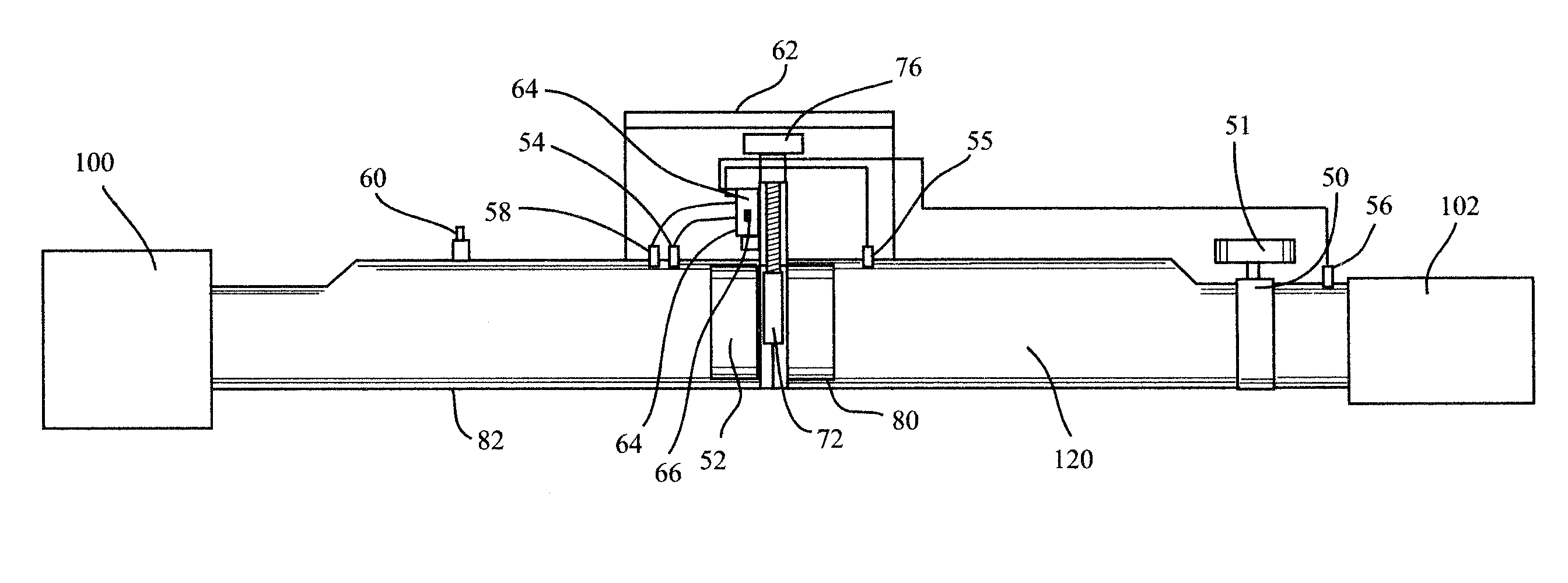
[0059]The principle of operation of the present invention is based on well-known fluid dynamic considerations. The first law of thermodynamics general energy equation can be used to relate the pressure loss resulting from fluid flow within a piping system to a specific flow rate. In flow rate measurement a restriction within a pipe is constructed which reduces the cross-sectional area of the pipe's traverse plane with respect to fluid flow. The pressure difference measured at the upstream and down streamside of the restriction, known as differential pressure, is used to determine the flow rate of the fluid. The unique flow rate is also dependant upon the cross sectional area of the restriction, the geometry of the piping system up and downstream of the restriction, as well as the fluid characteristics.

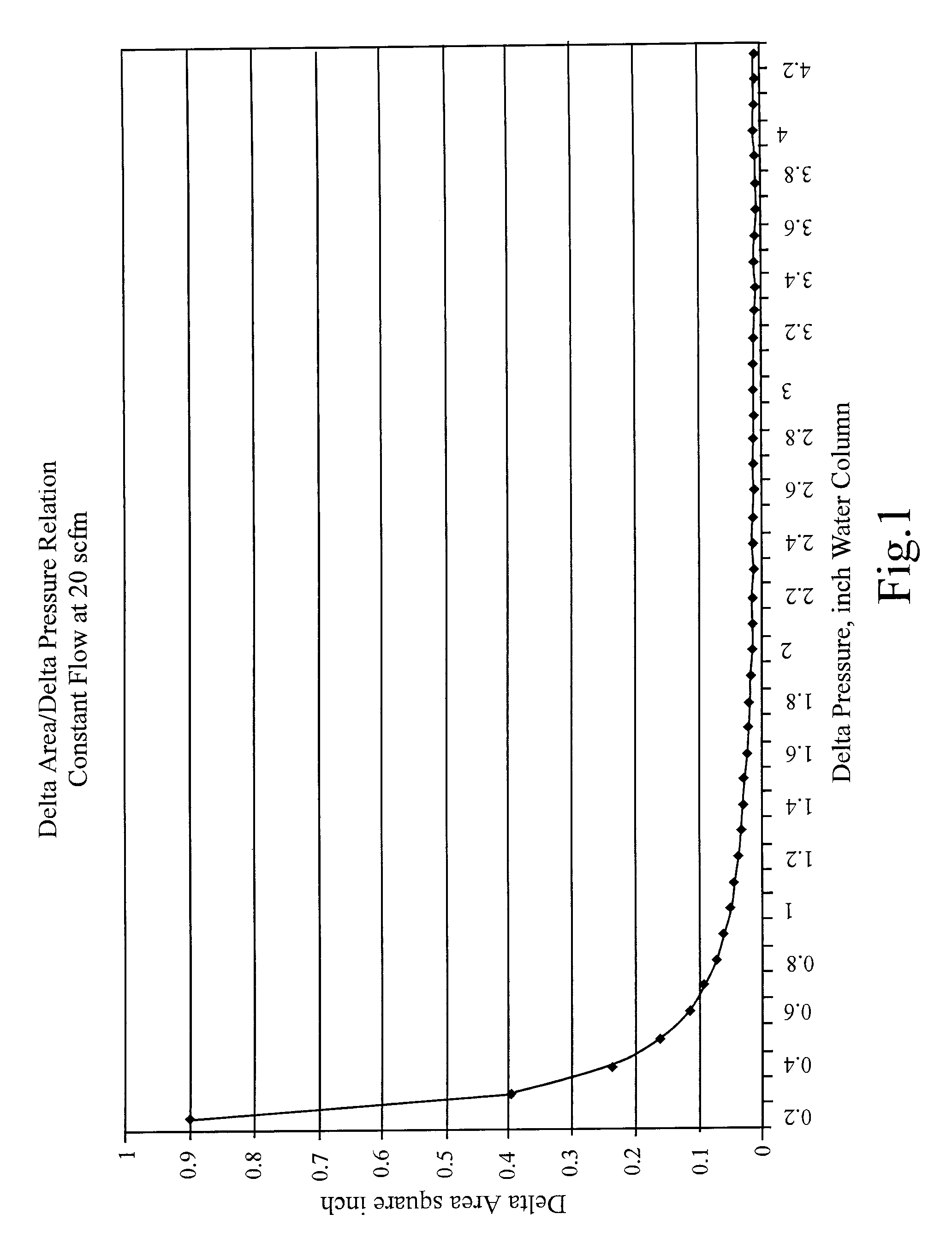
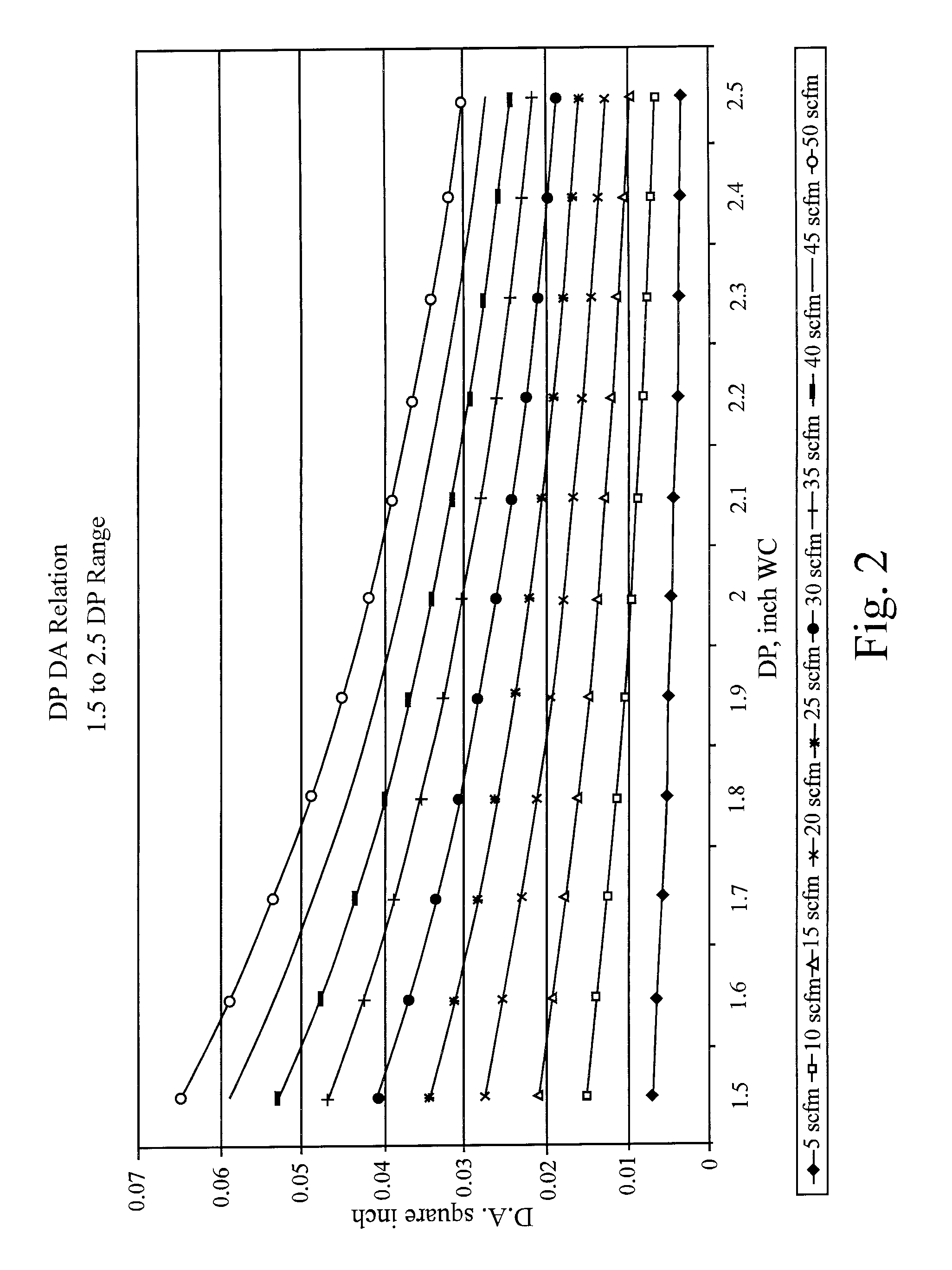
[0060]In a situation where the flow rate, gas characteristics, and pipe geometry are held constant, an inter-relationship will exist between cross sectional area of the restriction and...


PUM


Abstract

A control method and apparatus for regulating gas flow from landfill gas wells uses a differential pressure-regulating valve to maintain a set flow through a constant flow wellhead assembly. This wellhead assembly maintains a constant flow from the well despite normal variations in environmental factors affecting gas flow. The wellhead assembly includes a second valve that is used in series with the pressure-regulating valve to adjust the operating conditions of the regulating valve to keep it within its operating range. The pressure-regulating valve configuration allows a simple automatic control to position the valve. Periodic manual sampling of extracted gas and adjustment of the valve conditions is used to adjust for longer-term variations in well conditions.

Description

CROSS REFERENCE TO RELATED APPLICATIONS[0001]This application is a continuation-in-part of U.S. Non-provisional patent application Ser. No. 10 / 098,672 “Landfill Gas Extraction Constant Flow Control Method and Device” filed on Mar. 15, 2002 now abandoned, which is incorporated herein by reference.FEDERAL RESEARCH STATEMENT[0002]Not applicableBACKGROUND OF INVENTION[0003]1. Field of the Invention[0004]This invention relates to a control method and apparatus for optimizing the extraction of decomposition gas from solid waste landfills. More specifically, the present inventions pertains to a method using a wellhead device that when installed and operated on a landfill gas extraction well will provide the capability to select and maintain a constant flow rate of gas extraction from the subsurface. This capability allows controlling the extraction at near the gas generation rate for the well. The device also includes a high temperature shutdown feature in which the wellhead will stop gas ...

Claims


Application Information

Patent Timeline
IPC IPC(8): G01L7/00G01N11/00
CPCB09B1/006E21B34/02G01N1/2294G05D7/0635E21B43/12Y02E50/343Y02E50/30
Inventor BRADY, JOHNPOWELL, GREG S.MARKS, ROBIN
Owner MARKS & NOVA BALL MARKS TRUSTEES OR SUCCESSORTRUSTEE OF THE MARKS FAMILY TRUST UAD 5 13 05 ROBIN
Why Eureka
Try Eureka