
Switchable capacitor and method of making the same

a technology of switchable capacitors and capacitors, which is applied in the field of switchable capacitors and the method of making the same, radio frequency mems, can solve the problems of deterioration of insertion loss, degradation of effective down capacitance, and increase of insertion loss of shunt switches, so as to increase the down/up capacitance ratio

Active Publication Date: 2006-02-21
INTERUNIVERSITAIR MICRO ELECTRONICS CENT (IMEC VZW)
View PDF10 Cites 47 Cited by
  • Summary
  • Abstract
  • Description
  • Claims
  • Application Information

AI Technical Summary

Benefits of technology

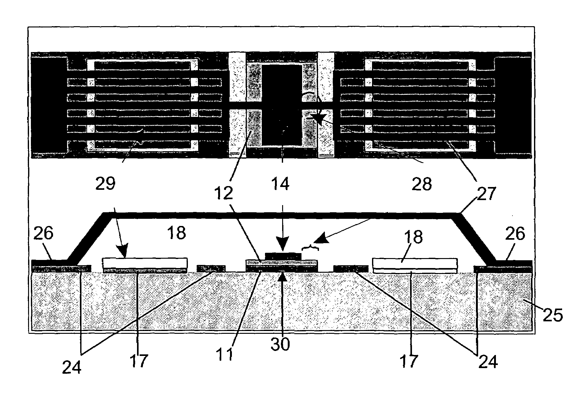
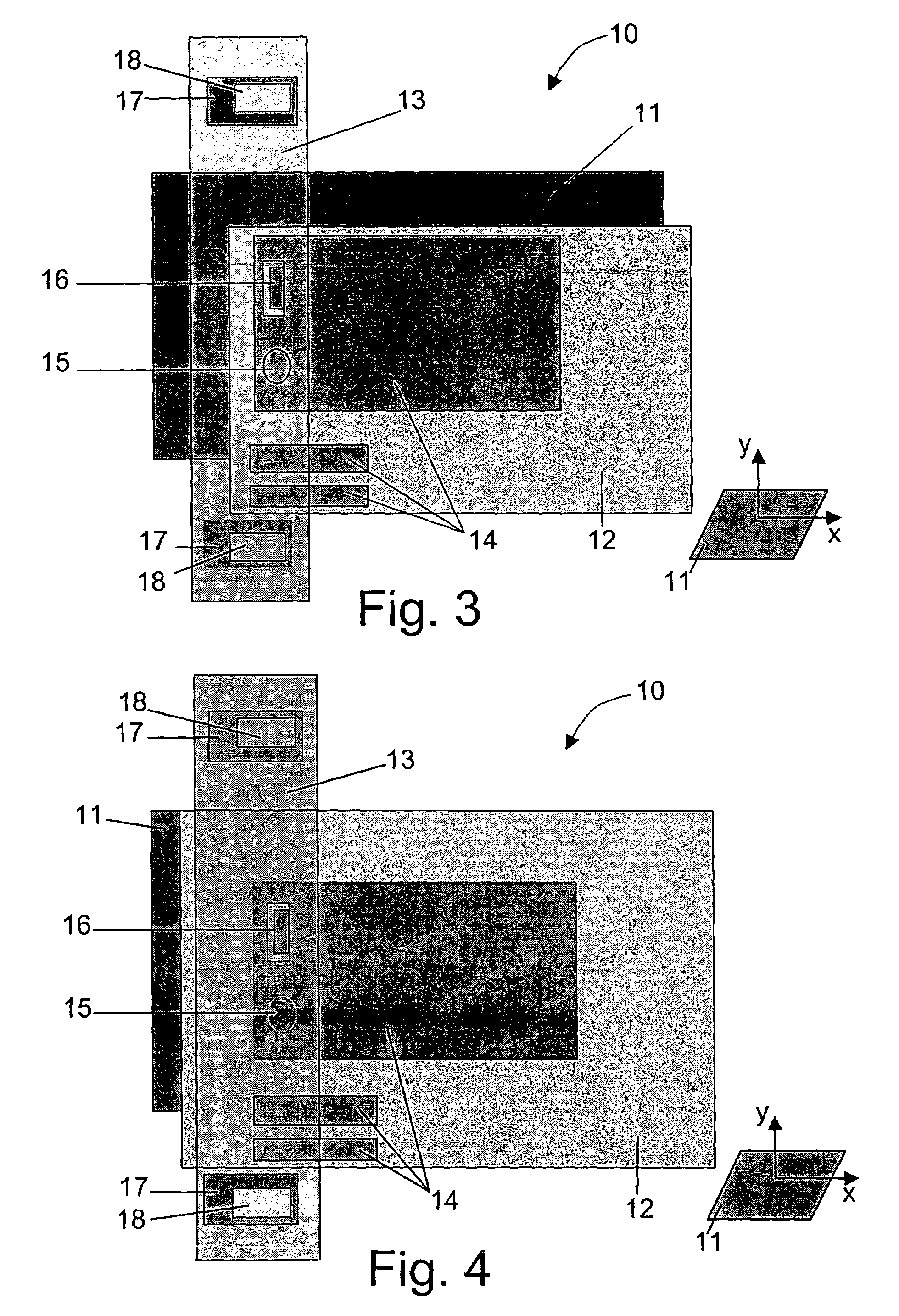
[0031]An advantage of the present invention is that by modifying the geometry of the device of the present invention, it is possible to increase the down / up capacitance ratio, which ratio is an important feature of a switchable capacitor.

Problems solved by technology

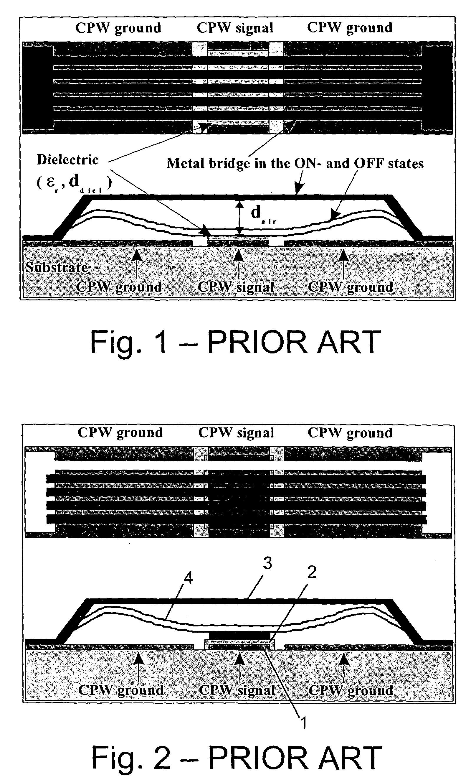
A second problem encountered in capacitive switches of the type shown in FIG. 1 is the degradation of the effective down capacitance as a result of surface roughness preventing intimate contact between the beam and the dielectric, which is discussed by J. B. Muldavin and G. M. Rebeiz in “High-isolation CPW MEMS shunt switches-Part 1: Modeling”, IEEE Trans.
All these measures however lead to a high series resistance and hence to an increased insertion loss for a shunt switch.
Obviously, in a standard design as the one shown in FIG. 1, a difficult compromise must be made as measures for improving the isolation directly lead to a deterioration of the insertion loss.
A problem with this device is that charging of the metal cap will reduce the force exercised on the bridge 3, which might bounce back into the original position, hereby disturbing the normal working of the switch.

Method used


Image

  • Switchable capacitor and method of making the same
  • Switchable capacitor and method of making the same
  • Switchable capacitor and method of making the same

Examples


Embodiment Construction

[0041]The present invention will be described with respect to particular embodiments and with reference to certain drawings but the invention is not limited thereto but only by the claims. The drawings described are only schematic and are non-limiting. In the drawings, the size of some of the elements may be exaggerated and not drawn on scale for illustrative purposes. Where the term “comprising” is used in the present description and claims, it does not exclude other elements or steps.

[0042]Furthermore, the terms first, second, third and the like in the description and in the claims, are used for distinguishing between similar elements and not necessarily for describing a sequential or chronological order. It is to be understood that the terms so used are interchangeable under appropriate circumstances and that the embodiments of the invention described herein are capable of operation in other sequences than described or illustrated herein.

[0043]Moreover, the terms top, bottom, ove...


PUM


Abstract

A micro electromechanical switchable capacitor is disclosed, comprising a substrate, a bottom electrode, a dielectric layer deposited on at least part of said bottom electrode, a conductive floating electrode deposited on at least part of said dielectric layer, an armature positioned proximate to the floating electrode and a first actuation area in order to stabilize the down state position of the armature. The device may furthermore comprise a second actuation area. The present invention provides shunt switches and series switches with actuation in zones attached to the floating electrode area or with relay actuation.

Description

RELATED APPLICATIONS[0001]This application claims priority to, and hereby incorporates by reference the entire, co-pending U.S. Provisional Application No. 60 / 410,954 entitled “Switchable Capacitor”, filed on Sep. 16, 2002.BACKGROUND OF THE INVENTION[0002]1. Field of the Invention[0003]The present invention relates to electronic devices, especially micro electromechanical (MEMS) devices and method of making the same. In particular the present invention relates to the field of radio frequency MEMS and more particularly the present invention relates to MEMS near-DC to RF capacitive shunt and series switches, e. g. a switchable capacitor.[0004]2. Description of the Related Art[0005]RF-MEMS switches offer great potential benefits over GaAs MMICs and PIN (positive intrinsic negative) diode switches for application in wireless communication systems as described by C. T. C. Nguyen, et al. , in “Micromachined devices for wireless communications”, Proc. of the IEEE, vol. 86(8), 1998, pp. 175...

Claims


Application Information

Patent Timeline
IPC IPC(8): H01P1/10H01P1/00H01H59/00
CPCH01H59/0009H01G5/16H01G5/18B81B3/001B81B2201/016B81C2201/115
Inventor ROTTENBERG, XAVIERJANSEN, HENRITILMANS, HENDRIKUSDE RAEDT, WALTER
Owner INTERUNIVERSITAIR MICRO ELECTRONICS CENT (IMEC VZW)
Learn More