Diagnostic method for high sensitivity detection of component concentrations in human gas emissions

Inactive Publication Date: 2006-02-28
PRANALYTICA
View PDF21 Cites 43 Cited by
  • Summary
  • Abstract
  • Description
  • Claims
  • Application Information

AI Technical Summary

Benefits of technology

[0019]The present invention provides a diagnostic method and apparatus for high sensitivity detection of trace component concentrations in human gas emissions such as exhaled breath and gas emitted through the skin. Trace concentrations of gases such as, for example, nitrogen oxides, ammonia, carbon dioxide, and chemical groups such as alcohols, ketones, and alkanes, may be detected and quantified. A sample of the human gas emissions which may contain the s

Problems solved by technology

Accordingly, the physical examination of a patient by a physician employing simply smelling of patient breath to gather information regarding the status of patient kidney function is impractical, save for the most severe cases.
A large fraction of these costs are attributable to present treatment methods which rely on regularly scheduled treatments for prescribed lengths of time.
Changing to a treatment protocol based on objective measures of treatment efficacy and efficiency will have a major impact on a very large and growing cost base.
Unfortunately, because of the difficulty in controlling the output of the source, and the need to have the light travel as great a distance as possible within a sample to maximize absorption, this process is incapable of easily measuring the concentration of trace components making up less than 1 ppm of a gas sample within a short time interval.
The second beam is passed through the test sample, where it is partially absorbed by the component in the test sample, resulting in an attenuation of the second beam's total energy.
The sensitivity afforded by this technique is, however, limited.
Therefore, the error margins present in the power measurements will have a larger effect on the calculation of the relatively small absorption amo

Method used


Image

  • Diagnostic method for high sensitivity detection of component concentrations in human gas emissions
  • Diagnostic method for high sensitivity detection of component concentrations in human gas emissions
  • Diagnostic method for high sensitivity detection of component concentrations in human gas emissions

Examples


Example

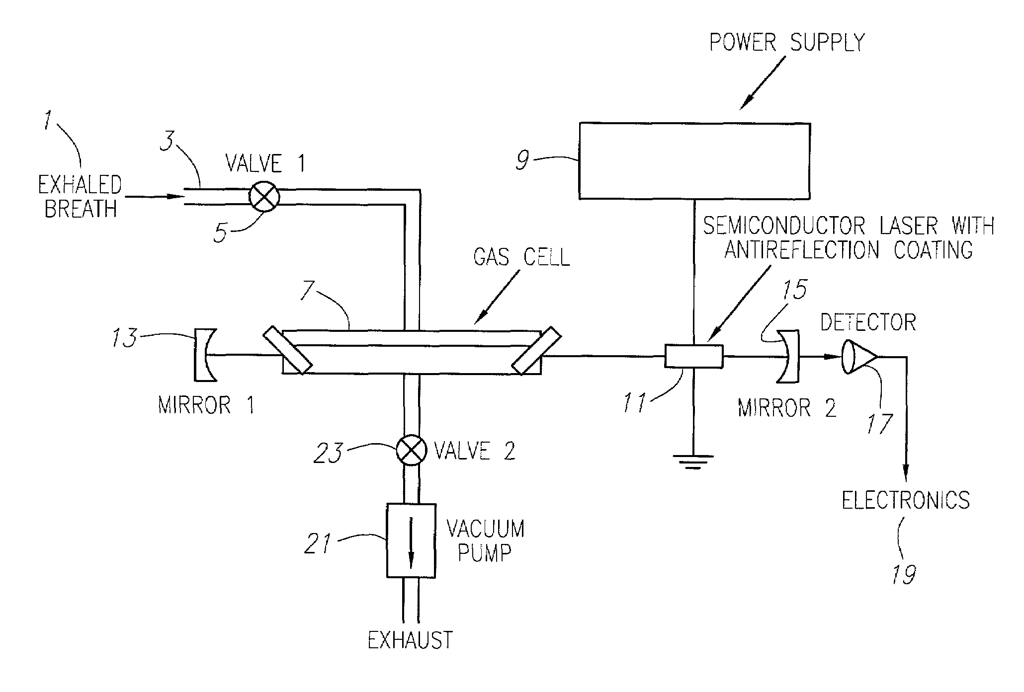
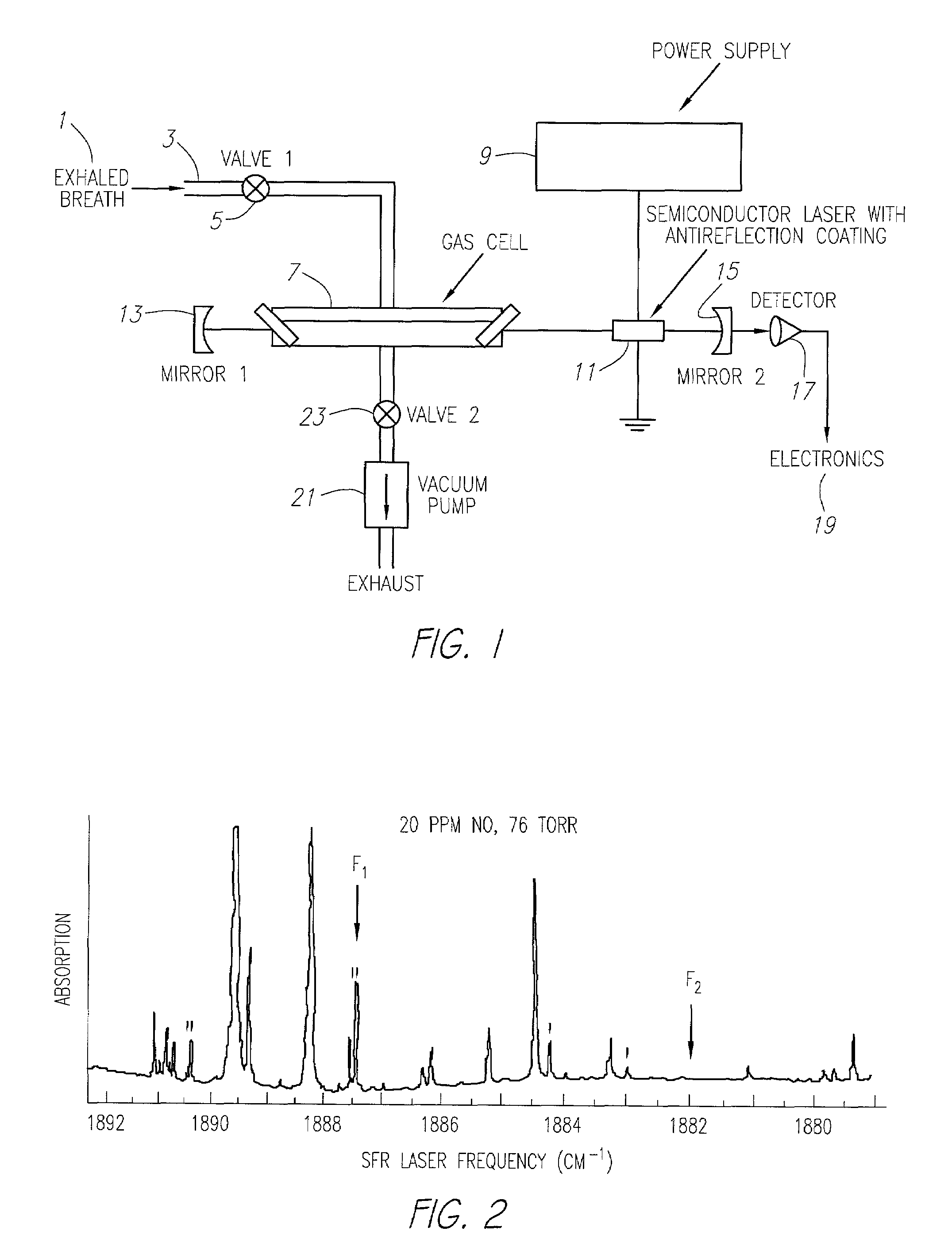
[0045]In the embodiment of the invention illustrated in FIG. 1, a gas sample of exhaled breath 1 suspected of containing a specified component is drawn through a conduit 3 and a valve 5, and into a gas cell 7 by means of a vacuum pump 21. The gas pressure in the gas cell 7 may be adjusted by the relative openings of the valves 5, 23, with the gas pressure preferably being between 10 Torr and 500 Torr.

[0046]A power supply 9 powers a tunable laser 11, preferably a semiconductor laser with an operational output of at least 1 mW (milliwatt), having anti-reflection coatings and capable of operating near at least one fundamental absorption peak frequency of the specified component being measured. A laser with an output of at least 1 mW enables the concentration of the specified component to be measured within approximately 1 ppB in approximately ten seconds of operating time. The type of laser used may vary depending upon the particular needs of the user and includes but is not limited to...


PUM


Abstract

A method for detecting component concentrations in human gas emissions such as breath and gas emitted from skin. A gas sample containing a specified component is collected into a gas cell using a pump and a series of valves to draw the gas sample into the cell and control the gas pressure within the cell. A tunable optical radiation beam is passed through the gas cell and the amount of energy absorbed by the specified component may be measured indirectly by taking the difference between the incident and emerging beam energy or directly by optoacoustic methods. Concentrations of the specified component as small as 0.1 ppB may be determined. Additionally, the tunable optical radiation beam may be multiplexed for use with a plurality of systems utilizing the beam for medical purposes.

Description

BACKGROUND OF THE INVENTION[0001]The field of this invention relates to absorption spectroscopy, more specifically, it pertains to medical uses of absorption spectroscopy to quantify component concentrations in human gas emissions, such as breath and gas emitted through the skin.Dialysis Population[0002]It is estimated that in the United States, approximately 246,000 patients underwent kidney dialysis treatment in 1999, “Living ESRD Patients on December 31,” Table D.1, United States Renal Data System (USRDS), 2000 ADR / Reference Tables, Section D—Treatment Modalities, www.usrds.org. Most of these patients undergo the treatment in clinics, hospitals, or specialized dialysis centers. However, a sizable number of the patients are able to avail themselves of dialysis through peritoneal dialysis treatments at home, Id. The typical kidney dialysis station costs approximately $25,000. For an effective deployment of such an investment, it is necessary to treat patients as efficiently as poss...

Claims


Application Information

Patent Timeline
IPC IPC(8): A61B5/00A61B10/00G01N21/31G01N21/39
CPCG01N21/39G01N21/314A61B2010/0083A61B2010/0087
Inventor PATEL, C. KUMAR N.NARASIMHAN, L. RAVI
Owner PRANALYTICA
Why Eureka
Try Eureka