
Circuit and method for an improved front end in duplex signal communication systems

a communication system and duplex signal technology, applied in the field of high-speed data communications on a two-wire transmission line, can solve the problems of consuming significant computing resources, twisted-pair loop impedances often straying dramatically from “typical”, and the entire balance network does not offer the flexibility required to match the impedance, so as to reduce the reflection of transmit signals

Inactive Publication Date: 2006-03-07
IKANOS COMMUNICATIONS
View PDF7 Cites 23 Cited by
  • Summary
  • Abstract
  • Description
  • Claims
  • Application Information

AI Technical Summary

Benefits of technology

"The patent describes an improved front end for a transceiver that reduces transmit signal reflections from entering the receive signal path. This is achieved by using a modified hybrid that includes a fixed portion and an adaptive portion to better match the varying impedance characteristics of two-wire twisted pair loops. The modified hybrid, when used in conjunction with a tuning algorithm, optimizes the recovery of a remotely generated signal from a duplex signal transmission on a two-wire transmission line. The front end can be adjusted during operation to compensate for environmental changes that may occur over time. The technical effect of this invention is to minimize transmit power requirements at remote transmitters and to provide a more efficient and effective solution for duplex communication."

Problems solved by technology

However, these fixed balance network hybrids suffer from the disadvantage that twisted-pair loop impedances often stray dramatically from “typical.” Stated another way, fixed balance networks do not offer the flexibility required to match the impedance of the various twisted-pair loops encountered in the public switched telephone network (PSTN) and other various networks that communicate via a two-wire pair.
Not only are fixed balance network hybrids disadvantageous when installed in association with a twisted-pair loop having one or more bridged taps, a different length or wire gauge, but changes in the loop impedance during operation result in less echo rejection of the local transmit signal from the receive path.
The Pecourt et al. solution of adaptively adjusting the entire balance network consumes significant computing resources.
Furthermore, Pecourt's methodology fails to take advantage of telephone industry standards that dictate the electrical properties of the line transformer and the tip and ring circuits.
The Pecourt et al. solution makes several assumptions, which lead to a problematic circuit that does not perform as Pecourt indicated when applied in an ADSL system.
As a result, the up-stream and down-stream data rates are limited by noise rather than transmission echo (as is the case for symmetric DSL services, which use the same frequency band for up-stream and down-stream signal transmissions), hence the noise level of any adaptive hybrid is crucial.
These two assumptions are incorrect: the high-pass filter impedance must be taken into account, and matching above 150 kHz cannot be ignored.
This interference will corrupt the receive signal unless it is suppressed by the hybrid.
It is true that the AGC gain is set mainly by the echo, but if the frequencies outside of the echo are drowned in transmit signal related noise, remotely generated signal transmissions will be difficult to recover.
Furthermore, when the requisite high-pass filter and isolation transformer are added, there are no degrees of freedom “left” for the bridged taps, etc.
In fact, Pecourt's solution does not offer sufficient flexibility to match the combination of the isolation transformer and high-pass filter.
Moreover, Pecourt's solution does not function above 150 kHz, where the remotely generated or receive signal gets corrupted by the local transmit signal noise and distortion.

Method used


Image

  • Circuit and method for an improved front end in duplex signal communication systems
  • Circuit and method for an improved front end in duplex signal communication systems
  • Circuit and method for an improved front end in duplex signal communication systems

Examples


Embodiment Construction

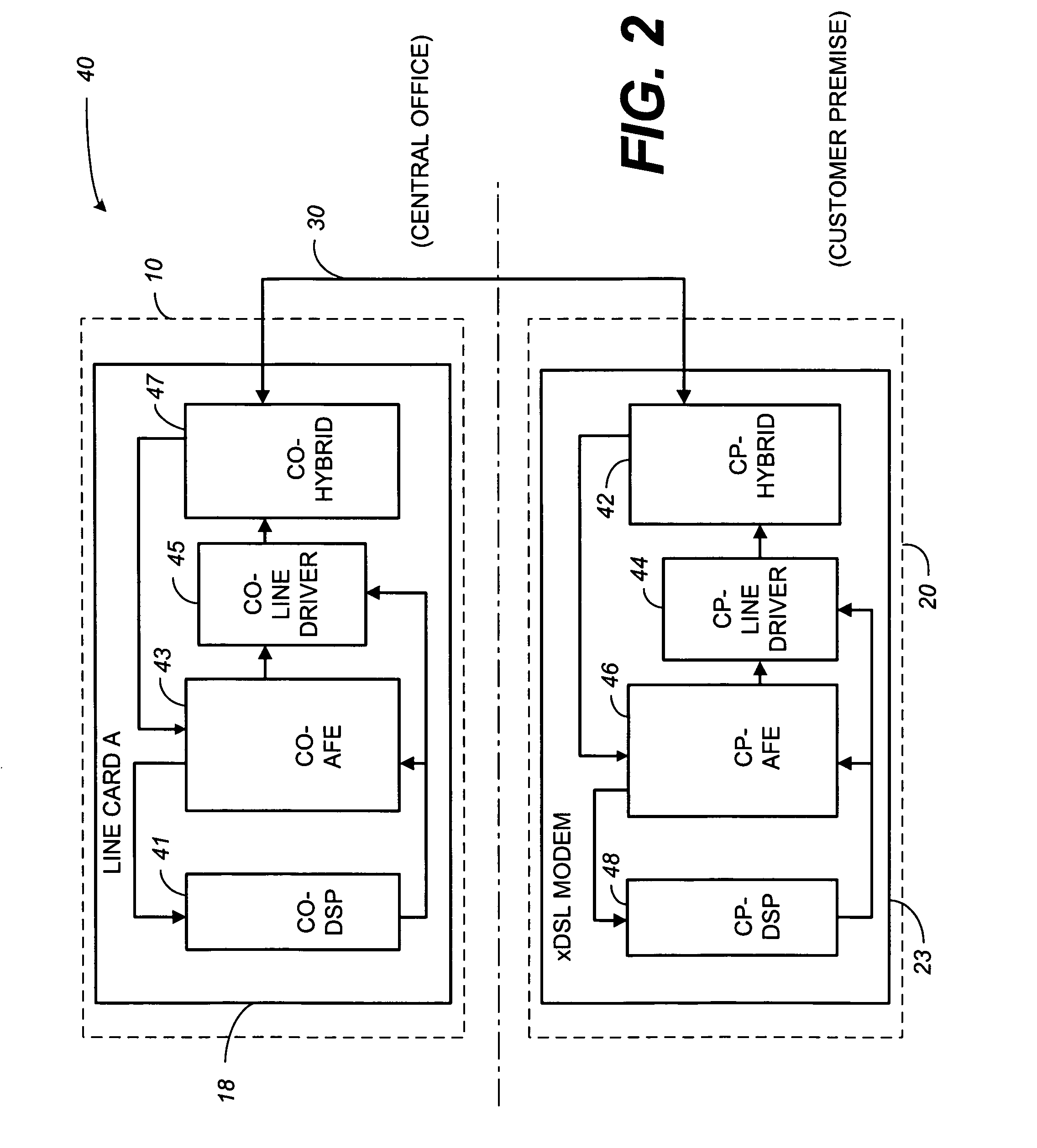
[0032]The detailed description presented herein focuses on elements from the perspective of a CP located printed circuit line card within a xDSL communication system. This explanation and description, however, are by way of example only. Those skilled in the art will appreciate that the concepts and teachings disclosed herein may be applied to various front ends as may be found in a plethora of various communication systems.

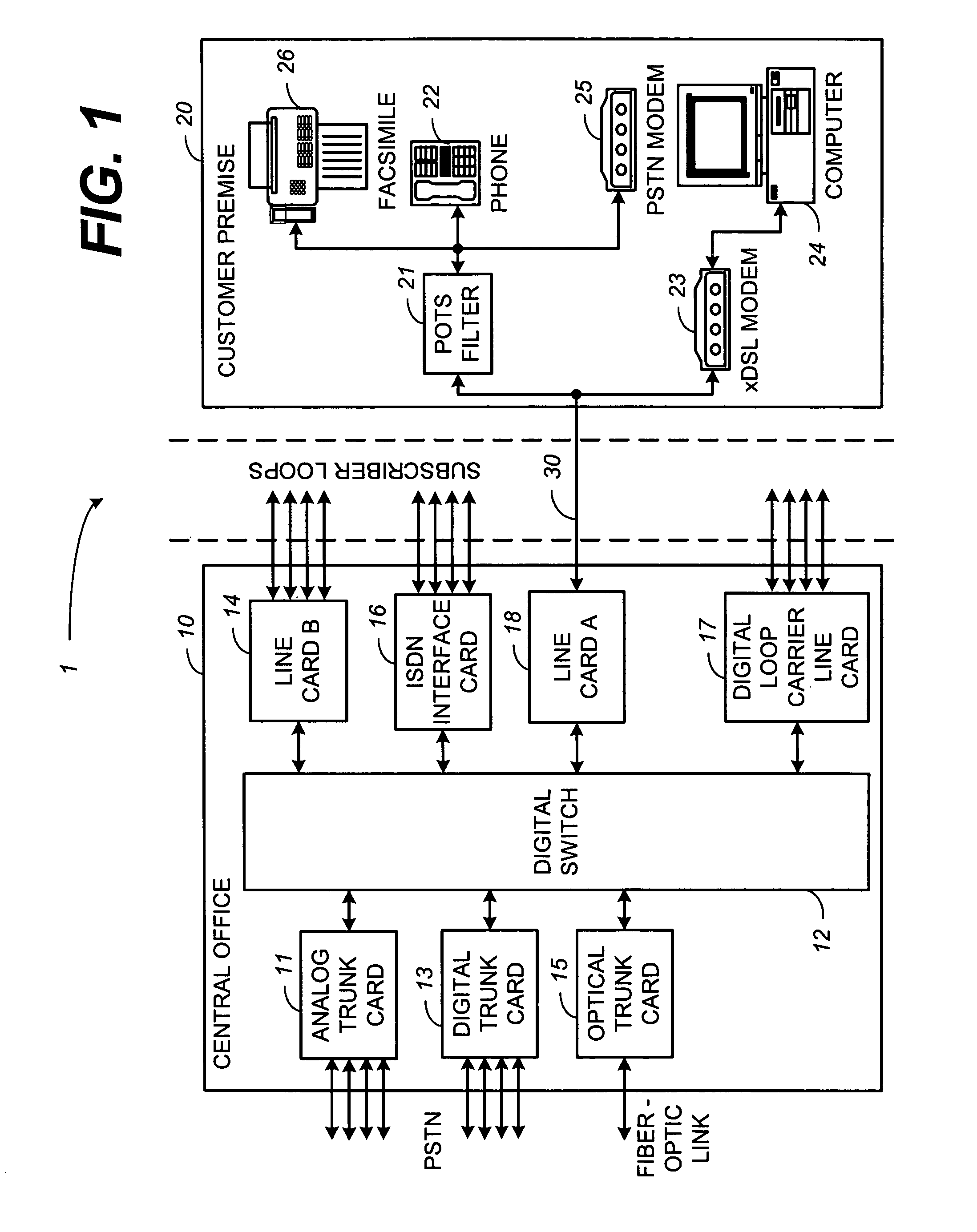
[0033]Turning now to the drawings illustrating the present invention, wherein like reference numerals designate corresponding parts throughout the drawings, reference is directed to FIG. 1, which illustrates a xDSL communication system 1. Specifically, FIG. 1 illustrates communication between a central office (CO) 10 and a customer premise (CP) 20 by way of twisted-pair telephone line 30. While the CP 20 may be a single dwelling residence, a small business, or other entity, it is generally characterized as having plain old telephone system (POTS) equipment, such ...


PUM


Abstract

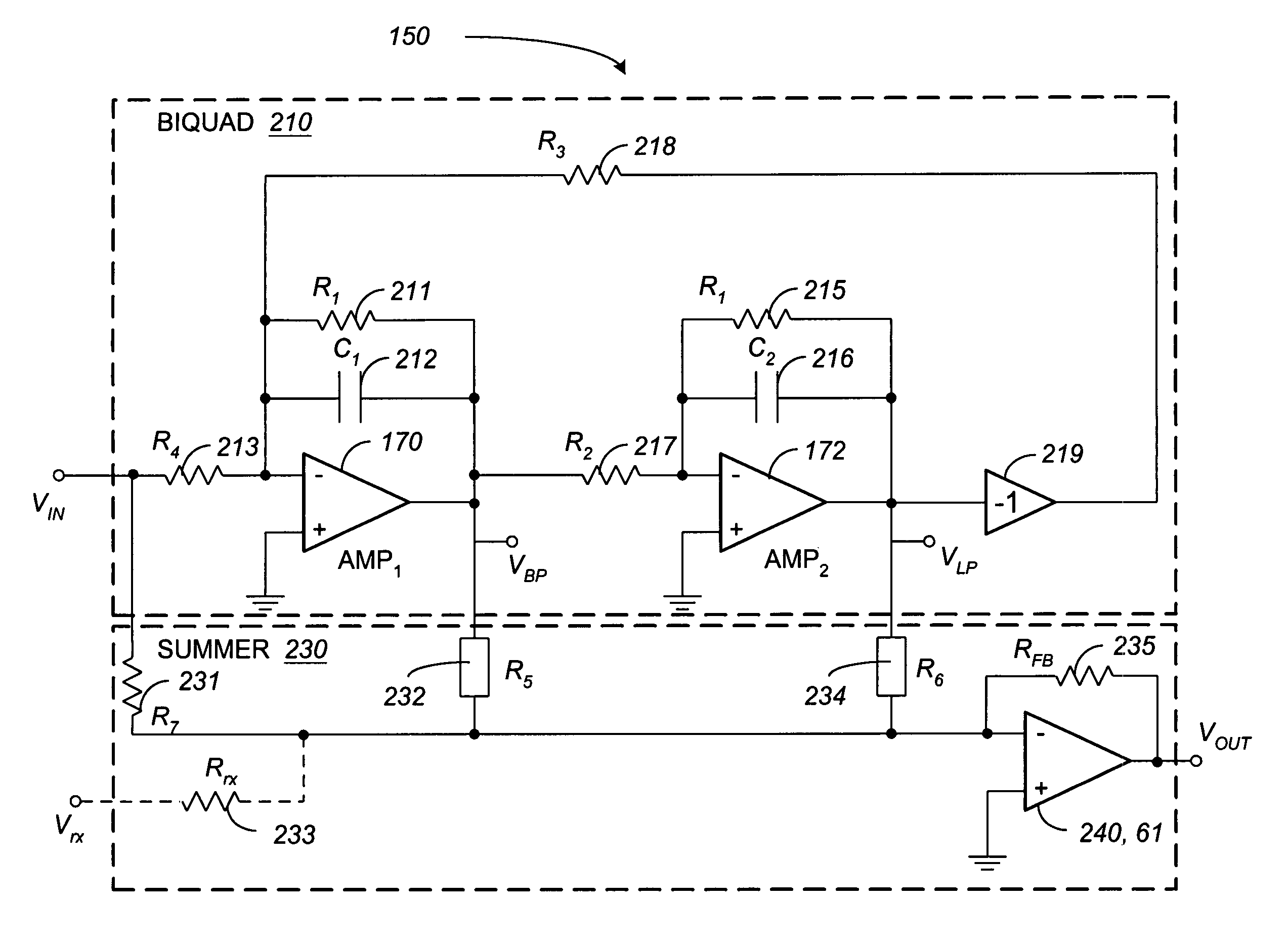
An improved analog front end and methods for increasing the power efficiency of duplex signals on a transmission line are disclosed. The improved analog front end bifurcates a hybrid into a fixed portion and an adaptive portion. The adaptive portion combines a biquad and a summer to produce a filter transfer function suited to compensate for transmission line irregularities. A method for configuring a local transceiver to minimize power requirements at a remote transmitter is disclosed. Broadly the method entails, applying a transmit signal to a front end in the absence of a remote signal; optimizing the transmit signal power; recording the reflected transmit signal; applying an adaptive filter in response to transmission line irregularities; and controllably adjusting the adaptive filter to minimize the amplitude of the reflected version of the transmit signal in the receive path. A method for recovering a remotely generated signal is also disclosed. The method entails, applying a local transmit signal to the front end in the absence of a remote signal; recording a reflected version of the transmit signal in the receive path; controllably adjusting an adaptive portion of the front end to minimize the amplitude of the reflected version of the local transmit signal; and combining a scaled replica of the local transmit signal with a plurality of adaptive filter outputs to recover a remotely generated receive signal from the transmission line.

Description

CROSS-REFERENCE TO RELATED APPLICATION[0001]The present application claims the benefit of co-pending U.S. Provisional Patent Application, issued Ser. No. 60 / 206,034, and filed May 22, 2000, which is hereby incorporated by reference in its entirety.FIELD OF THE INVENTION[0002]The present invention generally relates to high-speed data communications on a two-wire transmission line. More specifically, the invention relates to an improved front end, which solves problems associated with power efficiency, recovering receive signals from a duplex signal transmission, and impedance variances associated with two-wire transmission lines.BACKGROUND OF THE INVENTION[0003]With the advancement of technology, and the need for instantaneous information, the ability to transfer digital information from one location to another, such as from a central office (CO) to a customer premise (CP) has become more and more important.[0004]In a digital subscriber line (DSL) communication system, and more parti...

Claims


Application Information

Patent Timeline
Patent Type & Authority Patents(United States)
IPC IPC(8): H04B1/38H04L5/16
CPCH04B3/03H04B3/23
Inventor HELFENSTEIN, MARKUSLIM, DRAHOSLAVMOSCHYTZ, GEORGE S.MURALT, ARNOLD
Owner IKANOS COMMUNICATIONS
Learn More